Wiki
Clone wikiPCBmodE / Cordwood Puzzle assembly guide (for real!)
Welcome!
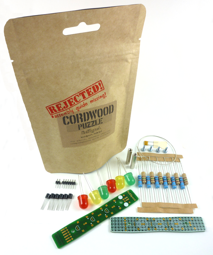
So you have a Cordwood Puzzle and need a bit of help with the assembly? Well, this is the missing assembly guide you've been looking for! The BoM for the circuit components is here.
The two boards are identical but function differently depending on how they are assembled/connected. The top side of the board is the side with the silkscreen pattern.
#Step 1: headers #
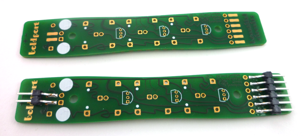
Choose one of the boards and solder the 6- and 2-pin SMD headers on it.
#Step 2: FETs#
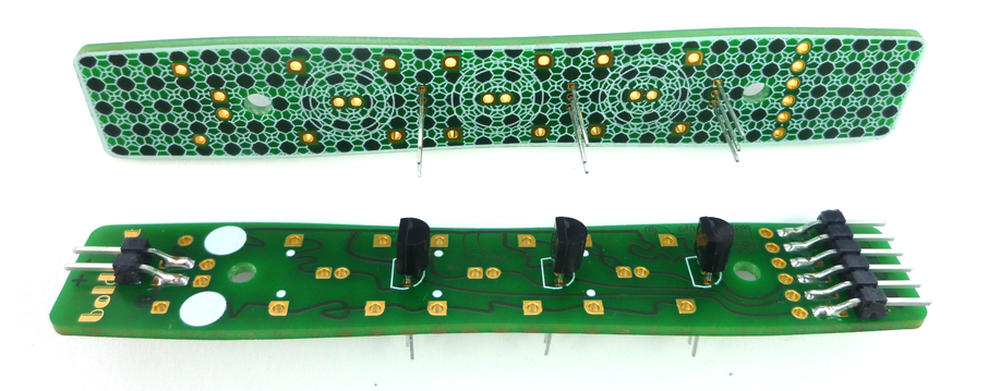
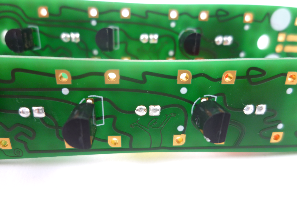
Insert the FETs into place from bottom side to top (note that they are not meant to go all the way through). Use the silkscreen as a guide to the orientation of the FETs. Solder the pins carefully so that there are no shorts.
The FETs can also be placed from the top if you prefer but make sure to get the polarity right!
Here's a soldering tip. Use cutters that can cut flush with the board
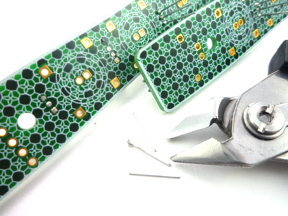
and then touch up the solder to create a smooth bump or nice round blob
#Step 3: LEDs#
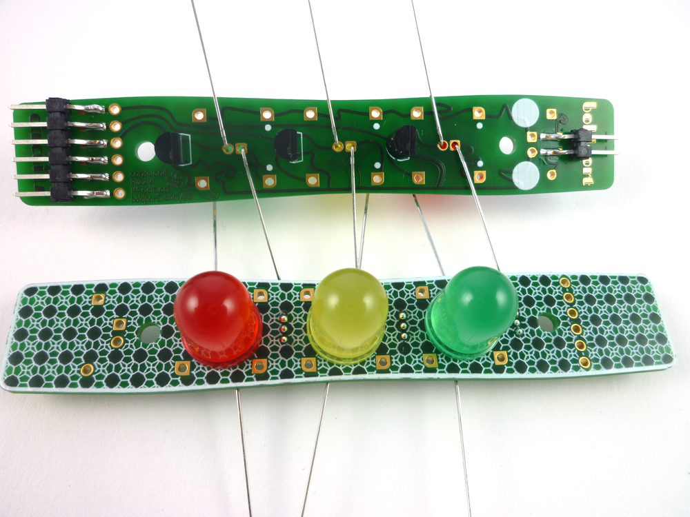
Insert the LEDs from top to bottom, making sure that the long lead ("anode") goes into the square pad on the PCB. Solder and clip the leads.
Hint: to get a sung fit, bend the leads before soldering.
#Step 4: Standoffs#
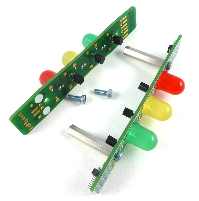
Take the board with the headers and screw in the standoff, but don't attach the other board just yet.
#Step 5: Resistors#
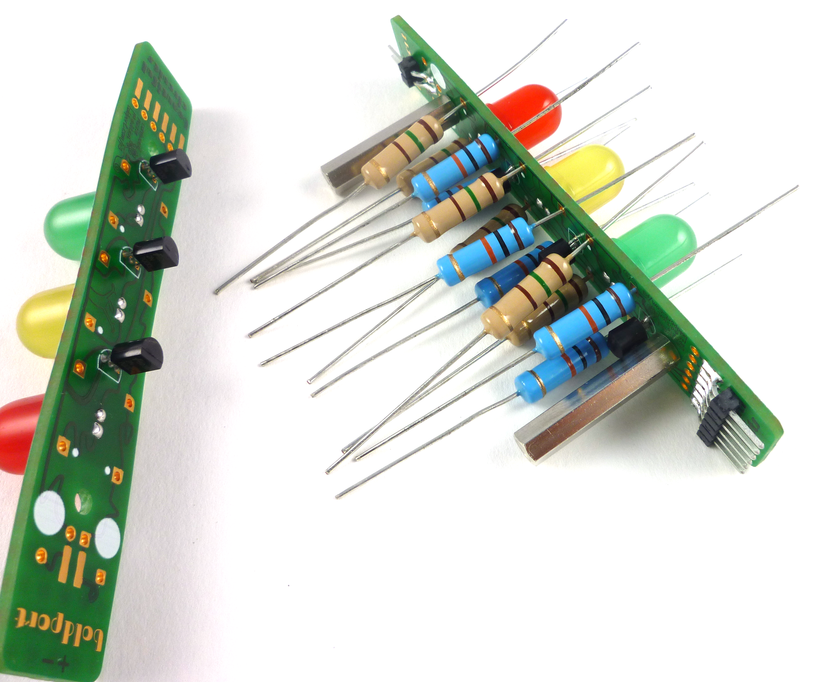
Each LED has four holes around it. With the board that the standoffs are attached to, place the 150 Ohm (brown) resistors, from bottom to top, into the holes with the silkscreen dot next to them and the 10 KOhm resistors (blue) into the holes without the dots.
#Step 6: Capacitor#
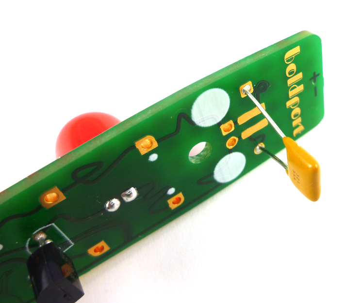
Inset the 1 uF capacitor into the holes that are to the right and left of the 2 pin header. This can be done on either board. If you have fancier >= 1 uF capacitors feel free to use them -- it's just there for some stability and local instantaneous current demand.
#Step 7: Assemble!#
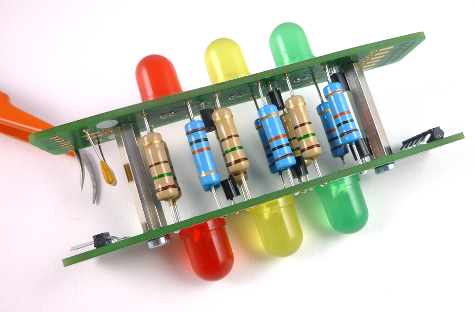
Align the other board and insert the resistors' "free" end into the corresponding holes. Then, affix the board to the standoff.
You can use a shorter standoff and resistors if you like. These are 2 W resistors, but they are there for the size, not their power rating!
#Step 8: Solder resistors#
For each resistor make sure that it is centred between the boards and solder the two ends into place. Again, bend the leads so that they don't move.
#Step 9: Connecting the two boards#
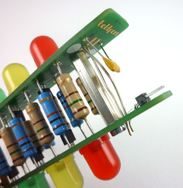
The '+' and '-' terminals need to be connected between the boards, which means that they need to cross. This is done with wires. Make sure that the wires cross but do not touch each other! If they do, then the power and ground will be shorted!
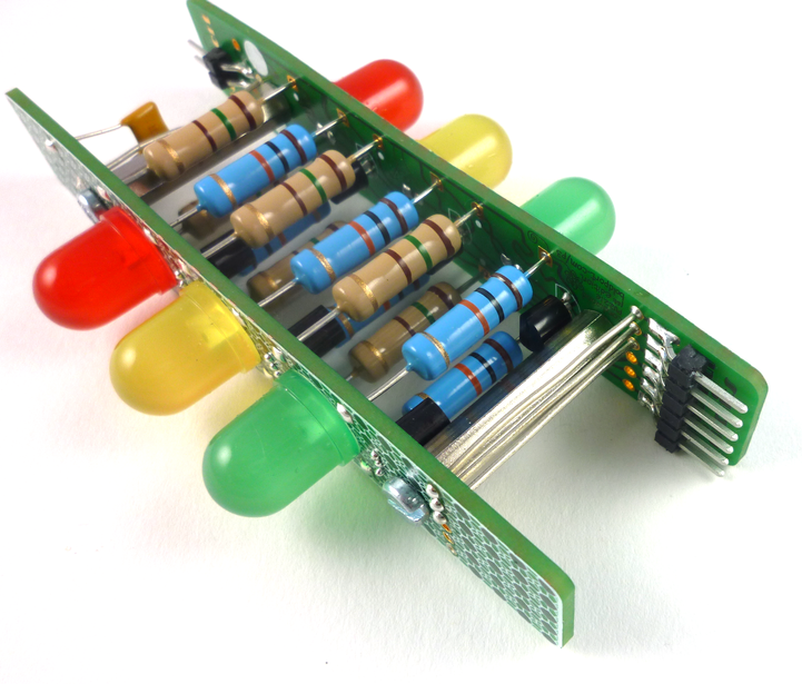
Now connect three signals from the board without the headers to the board with the headers, as shown. (These signals do not cross, and the holes match up.)
#Step 10: Done!#
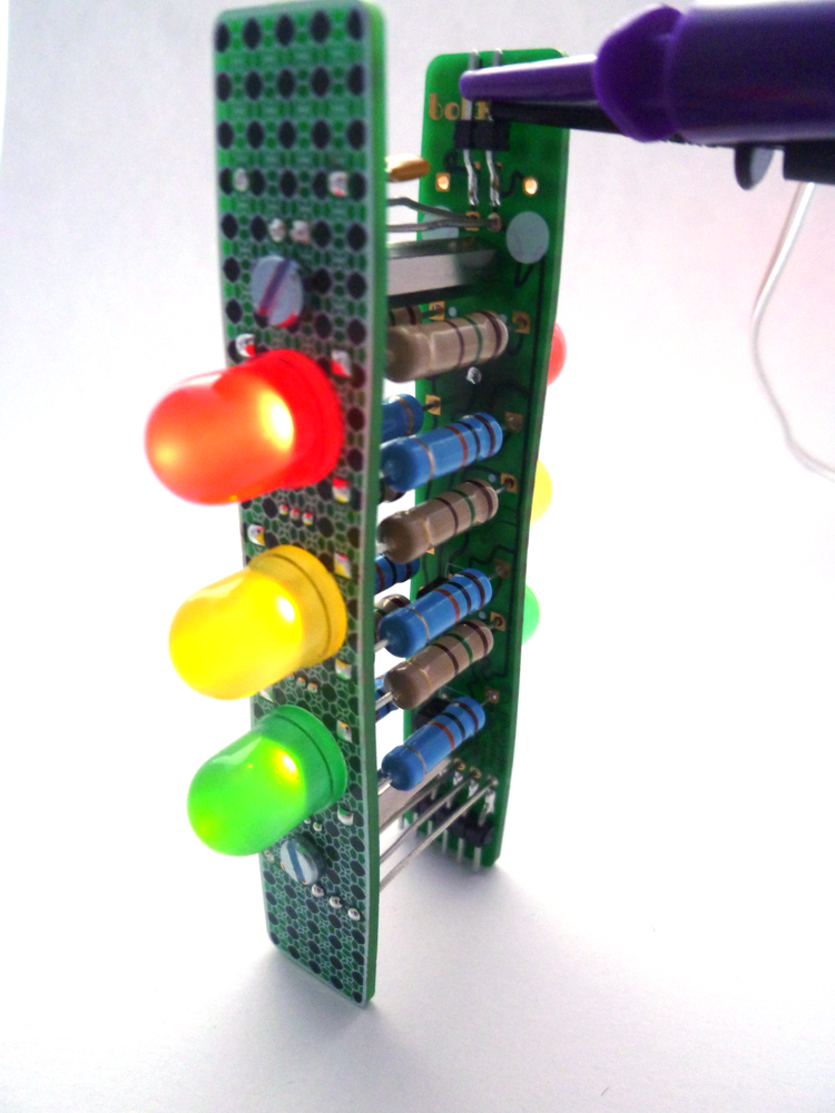
Now connect 5 V to the two header terminal -- the '+' and '-' are marked on the board -- and all LEDs should light up! You can also connect the board to a I/O-voltage-compatible board and control each LED individually. 3.3 V would work as well, but the light will be dimmer.
Enjoy!
Updated