Wiki
Clone wikiroseline / Tutorial 7 - Writing drivers for new peripheral devices
Overview
The objective of this tutorial is to show how one can interface the BeagleBoard Black with new peripherals. In particular, we will show how to modify the device tree, add kernel drivers and interact with devices within user space and without root permission.
Some things to keep in mind when using peripherals:
- The maximum voltage level on any digital pins is 3.3v. If you exceed this amount, there is a strong chance that your board will fail. You will know that it fails, because the single blue LED blinks once briefly on boot, then everything shuts off. A bricked board cannot be recovered and will need to be discarded.
- The maximum voltage level on any analogue pin is 1.8v.
- The maximum current draw on any digital pin is ~5mA.
- The maximum current draw on VDD 3.3V = 250mA
- The maximum current draw on VDD 5.0V = 1000mA
- The maximum current draw on SYS 5.0V = 250mA
- TCLKIN and CLKOUT2 are mutually exclusive.
- Be careful with the 3.3v / 5.0v source pins. They can easily be confused.
Pin multiplexing
The the heart of the BeagleBone Black is an OMAP AM3359 microcontroller with a very flexible I/O architecture. I say this because you are able to multiplex the same I/O device to many pins. This means that the board can be customised to suit your design needs.
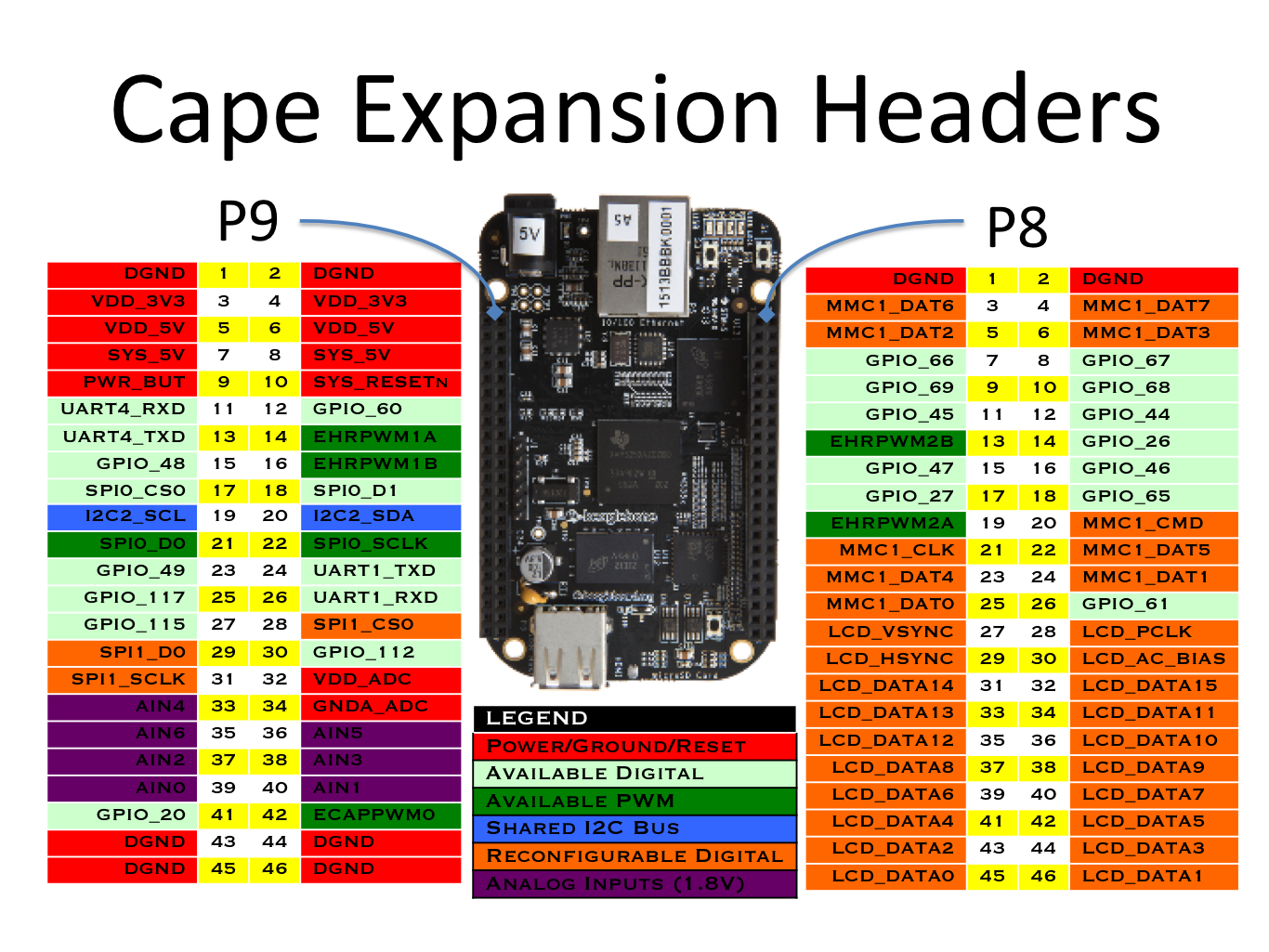
The Summary of the beaglebone black headers can be found here
The expansion header P8 and P9 of the board are as follows:

To setup pin multiplexing you will need a device tree compiler dtc. This compiler is part of the Linux source tree and activated automatically when you type make ARCH=arm dtbs. However, you can also build device trees outside of the kernel but you will need to checkout the dtc compiler code and have all of the patched template .dts and dtsi files for the am335x-boneblack, which is almost more work.
Assuming that you have a kernel source tree, the file you are interested in is located at <roseline>/kernel/linux/arch/arm/boot/dts/am335x-boneblack.dts. This file describes how to multiplex the pins for the bone black board. The device tree compiler converts this to am335x-boneblack.dtb, which you will recognise as the device tree file we used when booting the board.
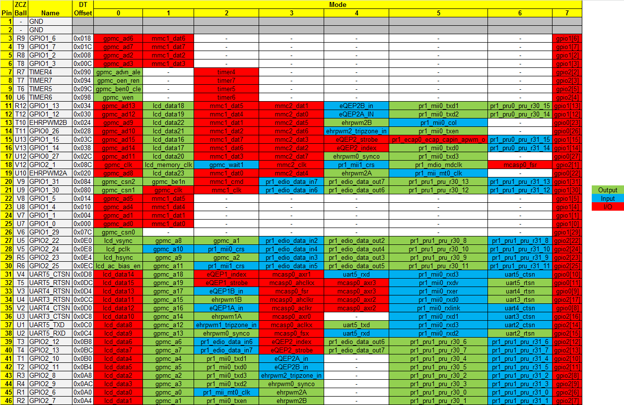
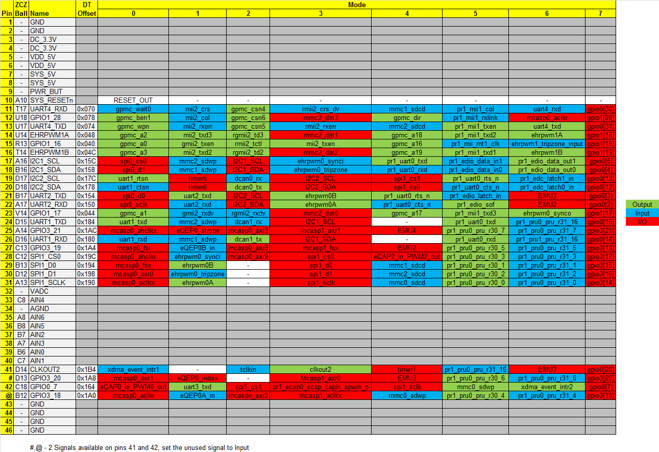
The most useful documents to help with setting up the multiplexing are the following spreadsheets.
P8:

P9:

Let's say for example that you want to light up an LED on P8.13. You find the correct row in the P8 spreadsheet, and see that it's device tree offset is 0x024 and the mode you will need to set it to is 7 to use it as just a normal GPIO (its default mode is EHRPWM2B). This translates to the following device tree entry:
&am33xx_pinmux {
    my_led_pin: my_led_pin {
        pinctrl-single,pins = <
                0x024 0x17      /* I_PULLUP | MODE7-GPIO0_23 */
        >;
    };
};
The 0x17 entry above is calculated from the bit layout below. In our case, we have requested a 0x17 == 0b010111, which translates to a MODE7 output pin that is pulled high by default.
- 5: [0] OUTPUT [1] INPUT
- 4: [0] PULLDOWN [1] PULLUP
- 3: [0] PULL ENABLED [1] PULL DISABLED
- 2: MODE
- 1: MODE
- 0: MODE
For those who are interested, this article explains pin muxing in much greater depth. One thing to watch out for are clashes between existing peripherals enabled by default and the new peripherals you are adding.
SPI Devices
Here is an example of how to set up a pin mux to enable SPI1 on P9.28 to P9.31, as well as enable a few I/O pins used by the external radio (AT86RF233).
&am33xx_pinmux {
    spi1_pins_s0: spi1_pins_s0 {
        pinctrl-single,pins = <
                0x040 0x37      /* DIG2  GPIO_9.15 I_PULLUP | MODE7-GPIO1_16 */
                0x044 0x17      /* SLPTR GPIO_9.23 O_PULLUP | MODE7-GPIO1_17 */
                0x1AC 0x17      /* RSTN  GPIO_9.25 O_PULLUP | MODE7-GPIO3_21 */
                0x1A4 0x37      /* IRQ   GPIO_9.26 I_PULLUP | MODE7-GPIO3_19 */
                0x190 0x33      /* SCLK mcasp0_aclkx.spi1_sclk, INPUT_PULLUP | MODE3 */
                0x194 0x33      /* MISO mcasp0_fsx.spi1_d0, INPUT_PULLUP | MODE3 */
                0x198 0x13      /* MOSI mcasp0_axr0.spi1_d1, OUTPUT_PULLUP | MODE3 */
                0x19c 0x13      /* SCS0 mcasp0_ahclkr.spi1_cs0, OUTPUT_PULLUP | MODE3 */
        >;
    };
};
Once the pins are enabled you also need to enable the SPI1 device -- the pinctrl-0 argument in the tree specifies the pinmux attached to the SPI1 interface (defined above). The compatible = "atmel,at86rf233"; argument tells the kernel that there is some module that works with this SPI device. In our case this is the at86rf230 module.
&spi1 {
    #address-cells = <1>;
    #size-cells = <0>;
    status = "okay";
    pinctrl-names = "default";
    pinctrl-0 = <&spi1_pins_s0>;
    at86rf233@0 {
        spi-max-frequency = <7500000>;
        reg = <0>;
        compatible = "atmel,at86rf233";
        interrupts = <19 1>;
        interrupt-parent = <&gpio3>;
        reset-gpio = <&gpio3 21 0>;
        sleep-gpio = <&gpio1 17 0>;
};
If you would prefer to have the SPI device presented as a raw character device to applications running in userspace, then you can use the compatible = "linux,spidev"; as below. This will create a device handle at /dev/spi1.0 representing the device.
&spi1 {
    #address-cells = <1>;
    #size-cells = <0>;
    status = "okay";
    pinctrl-names = "default";
    pinctrl-0 = <&spi1_pins_s0>;
    spidev@1 {
         spi-max-frequency = <24000000>;
         reg = <0>;
         compatible = "linux,spidev";
    };
}
Note that it is also possible to switch the MISO and MOSI lines, and enable multiple CS lines to multiplex between several SPI peripherals on the same interface. Please refer to this documentation for more information.
Example application code: click here
I2C Devices
I2C devices are enabled in a similar way to SPI devices. Again, you create a pinmux to specify which pins the I2C interface will work on. This time, however, you reference the pinmux from a handle to a specific I2C device. For example, of we would like I2C specified as MODE3 on P9.24 and P9.26 this is our pinmux:
&am33xx_pinmux {
    bb_i2c1_pins: pinmux_bb_i2c1_pins {
       pinctrl-single,pins = <
       0x184 0x73      /* uart1_ctsn.i2c2_sda, SLEWCTRL_SLOW | INPUT_PULLUP | MODE3 */
       0x180 0x73      /* uart1_rtsn.i2c2_scl, SLEWCTRL_SLOW | INPUT_PULLUP | MODE3 */
  >;
};
We then provide an overlay for i2c1 that references our newly-created pinmux. The result of this will be a character device at /dev/i2c1 that can be interacted with from userspace.
&i2c1 {
       #address-cells = <1>;
       #size-cells = <0>;
       status = "okay";
       pinctrl-names = "default";
       pinctrl-0 = <&bb_i2c1_pins>;
       clock-frequency = <100000>;
};
Example application code: click here
UART Devices (serial lines)
Unsurprisingly, serial lines work in a similar way to both SPI and I2C. Again, you define a pinmux for the RX and TX lines. For example, let's say you wish to enable UART4 on P9.11 (RX) and P9.13 (TX) then your pinmux would look like this:
&am33xx_pinmux {
    uart4_pins: pinmux_uart4_pins {
        pinctrl-single,pins = <
                0x70 0x26       /* P9.11 uart4_rxd MODE6 INPUT (RX)  */
                0x74 0x06       /* P9.13 uart4_txd MODE6 OUTPUT (TX) */
        >;
    };
Then you overlay the uart4 device handle, referencing the pinmux we just specified. The result of this will be a character device labelled /dev/tty04. Once your peripheral is connected, you can open minicom and interact directly with this device.
&uart4 {
        status = "okay";
        pinctrl-names = "default";
        pinctrl-0 = <&uart4_pins>;
};
Example application code: click here
Updated