Wiki
Clone wikiART / Luts
![]()
Working with LUTs
ART has inherited from RawTherapee the support for creative 3D LUTs in the form of Hald CLUTS, available in the Film Simulation tool. Starting from version 1.16, however, the support for LUTs has been significantly enhanced.
In particular, now ART supports two new kinds of LUTs which can be used to encode various powerful and flexible pixel-level operations:
-
ACES CLF LUTs, thanks to the use of OpenColorIO v2 (OCIO for short);
-
Scripts written in the Color Transformation Language (CTL), thanks to the use of the ACES CTL interpreter (since version 1.21).
Both kinds of LUTs must be enabled at compile time, by setting respectively ENABLE_OCIO and ENABLE_CTL to True in CMake.
When available, they can be used in both the "Film Simulation" and in the the "Color/Tone Corrections" modules.
CLF LUTs
Despite the name, CLF LUTs are not simply look-up tables, but can encode a sequence of different pixel-level operations, including matrix multiplications, ASC CDL operations, and per-channel transfer functions. What this means is that they are well suited to be applied in a scene-referred workflow, e.g. to implement "look transforms" or also "output transforms" (i.e. tone mapping operations from scene to display/output). For example, now it is possible to apply ACES output transforms directly in ART, or even color grade pictures using look+output LUTs developed for high-end professional cinema cameras.
The only thing needed is to convert such LUTs to CLF and combine them with the appropriate color space conversions to/from ACES 2065-1 (which is the color space used by ART to apply CLF LUTs), all of which can be done with OCIO tools and a little bit of scripting.
Generating ART-compatible CLF LUTs
The OCIO distribution comes with ociomakeclf, a command-line tool to convert many LUT formats to CLF. Conveniently, ociomakeclf can also perform color space conversions from the space required by the LUT to ACES 2065-1, which is what ART assumes, via the --csc parameter.
For many "creative-type" LUTs, which do not change the color space of the input image, invoking ociomakeclf with the appropriate value for --csc is all that is needed.
For example, converting one of the ARRI Look LUTs in LogC3 space to CLF in ACES 2065-1 can be done by using --csc ARRI_ALEXA-LOGC-EI800-AWG, whereas for RED Creative LUTs, instead, --csc RED_LOG3G10-RWG should be used.
The process is a bit more involved for LUTs that also perform color space conversions of their inputs, such as the LUTs used to implement output transforms in various scene-referred pipelines typically used in video editing such as ACES. In this case, the steps needed are as follows:
- Generate a CLF LUT for converting from ACES 2065-1 to the input format expected by the LUT;
- Convert the LUT to CLF via
ociomakeclf, but without any color space conversion; - Generate a CLF LUT for converting from the output format produced by the LUT;
- Combine the three LUTs above into a single one.
For example, the current output transform candidates for ACESv2 take as input an image with ACES AP0 primaries, but logarithmically encoded values using the ACEScct formula. Therefore, in step 1. we need to convert from linear ACES AP0 (i.e. ACES 2065-1) to ACEScct with AP0 primaries, which can be done with the following CLF LUT (let's call it ACES-2065-1_to_ACEScct-AP0.clf):
<?xml version="1.0" encoding="UTF-8"?>
<ProcessList compCLFversion="3" id="1">
  <!-- convert from linear AP0 to ACEScct with AP0 primaries -->
  <Log inBitDepth="32f" outBitDepth="32f" style="cameraLinToLog">
    <LogParams base="2" linSideSlope="1" linSideOffset="0" logSideSlope="0.0570776255707763" logSideOffset="0.554794520547945" linSideBreak="0.0078125" />
  </Log>
</ProcessList>
For step 3, assuming we want to use the "Rec.709" version of the output transforms (which is suitable for a standard SDR display), we can use the following CLF to convert from Rec.709 with a 2.4 gamma to ACES 2065-1 (let's call it Rec709_to_ACES-2065-1.clf):
<?xml version="1.0" encoding="UTF-8"?>
<ProcessList compCLFversion="3" id="3">
    <Exponent inBitDepth="32f" outBitDepth="32f" style="basicFwd">
      <!-- rec1886 EOTF -->
      <ExponentParams exponent="2.4"/>
    </Exponent>
    <Matrix inBitDepth="32f" outBitDepth="32f" >
      <!-- Linear Rec.709 to ACES AP0-->
      <Array dim="3 3">
        0.43392843 0.3762503  0.18982151
        0.088802   0.81526168 0.09593625
        0.01775005 0.10944762 0.87280228
      </Array>
    </Matrix>
</ProcessList>
Finally, for step 4, we can use this simple Python script to obtain our final result (RESULT.clf):
$ python combine_clf_luts.py ACES-2065-1_to_ACEScct-AP0.clf LUT.clf Rec709_to_ACES-2065-1.clf -o RESULT.clf
If you want to save space, you can also compress RESULT.clf using gzip, and then rename the file to RESULT.clfz:
$ gzip RESULT.clf && mv RESULT.clf.gz RESULT.clfz
Alternatively, you can also pass the -c flag to combine_clf_luts.py to generate a compressed LUT directly.
Note though that supporting gzip compression is an ART extension, so the compressed LUTs will probably not work with other OCIO-based apps.
Useful tools
Here are links to some useful tools for working with CLF LUTs.
CTL scripts
CTL (the Color Transformation Language) is a scripting language designed to create custom pixel-level image transformation operations. LUTs expressed as CTL scripts are even more powerful and flexible than CLF LUTs, allowing to define complex image manipulation operations as programs in a language similar to C or C++.
Importantly, CTL scripts in ART can be parametric:
by using specially-formatted comments in the script, users can declare that some arguments of the main function of the script are parameters
that can be changed directly from the ART GUI
(and whose values are stored in .arp sidecar files).
This provides a simple but powerful way of extending ART with user-written filters.
Writing ART-compatible CTL scripts
In order to be usable within ART, a CTL script must define a function called ART_main,
which is the entry point called by ART.
The function should take 3 varying input arguments of type float
and 3 corresponding varying output arguments, again of type float.
Such arguments correspond to the red, green and blue components of each pixel of the image being processed.
Specifically, the function will be called for every pixel of the input image,
which is in RGB format and normalized so that the SDR tonal range corresponds
to the [0, 1] interval (though the data might exceed such range both in
input and in output).
By default, the RGB values are encoded in the ACES 2065-1 color space,
but this can be overridden by inserting in the scritp an ART color space tag in the following form:
// @ART-colorspace: "<colorspace>"
where <colorspace> can be ACES2065-1 (default), ACEScg, Rec2020, Rec709, ProPhoto, or AdobeRGB.
Additionally, ART_main might take an arbitrary number of other uniform arguments of type int, float or bool,
which will be interpreted as parameters for the script.
Each such parameter must come with an
associated ART parameter definition in the CTL script. ART parameter
definitions are special comment lines of the following form:
// @ART-param: <param-def>
where <param-def> is an array in JSON format, whose content depends on the
parameter type. The array must be at least of size 2; the first element is
a string containing the name of the parameter (which must mach the name
used in ART_main), and the second element is its GUI label. The rest of the
array has the following structure:
-
for
boolparameters, the 3rd optional element specifies the default value; the optional 4th and 5th elements instead are respectively: -
a "group name" for the GUI: if set, this will cause the control to appear under a collapsible panel with the given name in the GUI;
-
a tooltip string for the GUI: if set, the given string in Pango markup format is used as a tooltip.
-
for
floatparameters, the array size must be at least 4 and at most 8. The 3rd and 4th elements are the minimum and maximum values for the GUI slider. The optional 5th element is the default value, the optional 6th element the precision to use in the GUI (e.g. 0.01 will use 2 decimal digits in the GUI), and the optional last two elements are the GUI group name and tooltip; -
for
intparameters, the array size must be at least 3 and at most 7. If the 3rd parameter is an array of strings, it is interpreted as a list of options in a choice menu, with values corresponding to their index in the array (i.e. the 1st option will give a value of 0, the 2nd a value of 1, etc.). In this case, the array can contain at most 3 other elements, which are respectively the default value and the optional GUI group name and tooltip.
If the 3rd parameter is not an array of strings, then the array size must be at least 4, with the 3rd and 4th elements corresponding to the minimum and maximum values for the GUI slider. The optional 5th element is the default value, and the optional last two elements are the GUI group name and tooltip.
If default values are not given in the ART parameter definition, they are
taken from the definition of the ART_main function. If no default is given,
zero is used.
Here is an example of parameter definitions for each of the supported types.
For param_float, besides the required minimum and maximum values, we also specify the default and the GUI precision;
for param_int, only the required elements are provided;
for param_bool, a default value of true is given;
finally, for param_choice, all the possible elements are provided.
// @ART-param: ["param_float", "A float slider", -1.0, 1.0, 0.5, 0.1]
// @ART-param: ["param_int", "An int slider", -10, 10]
// @ART-param: ["param_bool", "A checkbox", true]
// @ART-param: ["param_choice", "A combo box", ["Option A", "Option B"], 1, "Choice group", "Tooltip <b>using markup</b>!"]

void ART_main(varying float r, varying float g, varying float b,
              output varying float r_out, output varying float g_out, output varying float b_out,
              float param_float, int param_int, bool param_bool, int param_choice)
{
   // ...
}
Example
Here is a simple ART-compatible CTL script to perform exposure compensation. The script takes one parameter that gives the Ev value of the exposure correction to apply. The CTL code looks like this:
// @ART-param: ["expcomp", "Exposure compensation", -5.0, 5.0, 0, 0.1]

void ART_main(varying float r, varying float g, varying float b,
              output varying float r_out, output varying float g_out, output varying float b_out,
              float expcomp)
{
   const float scale = pow(2, expcomp);
   r_out = r * scale;
   g_out = g * scale;
   b_out = b * scale;
}
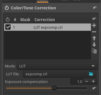
The corresponding GUI when loaded in ART (in the "Color/Tone Correction" tool) looks like this:
More complex examples
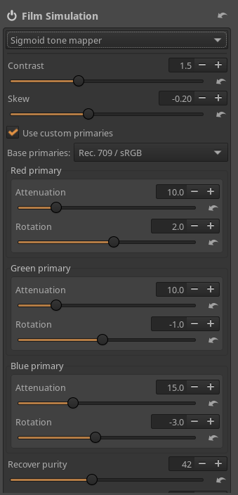
Starting from version 1.21, ART ships with a (slightly simplified) implementation of the Sigmoid tone mapper of darktable as a CTL script. This can be used as an alternative tone mapper for ART, and it is automatically available in the "Film Simulation" module (if CTL support was enabled at compile time):
A collection of other examples are available in this repository.
Making CTL scripts automatically available
CTL scripts placed in the ctlscripts subdirectory of the ART config folder
(typically $HOME/.config/ART on Linux and %LOCALAPPDATA%\ART on Windows)
are loaded automatically by ART upon startup,
and available as additional operation modes in the "Color/Tone Correction" tool.
For example, by putting our expcomp.ctl example in $HOME/.config/ART/ctlscripts, we have it as an additional mode:
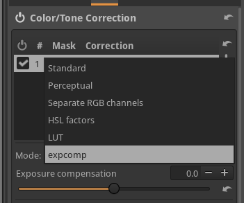
By default, the name of the file (without the .ctl extension) is used as mode name.
This can be customized by adding an ART label tag to the CTL script,
with the following format:
// @ART-label: "<toolname>"
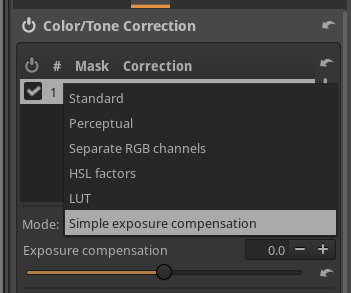
For example, by adding:
// @ART-label: "Simple exposure compensation"
to expcomp.ctl, we now get a nicer name in the GUI:
Updated