Wiki
Clone wikilifev-release / tutorial / Basics_of_mesh_generation
Basics of mesh generation
Mesh generation is a major task in the simulation workflow. In fact, after designing the geometry of the computational domain we need to mesh it in view of performing finite element simulations. LifeV currently offer support for 2D and 3D meshes generated using triangles and tetrahedral elements, respectively. In this tutorial we show how to generate the geometry and the mesh of a cube geometry: precisely
- Generate the geometry representing the computational domain
- Assign flags to the different boundaries of the domain (these flags will be used later on to assign boundary conditions in the finite element simulations)
- Generate the computational mesh using gmsh (thus, obtaining a .msh mesh file)
- Convert the mesh file from the gmsh (extension .msh) to the medit (extension .mesh) format
Geometry
The user may utilize Gmsh through its user interface or by scripts. In fact gmsh is scriptable so that all input data can be parametrized. The first step consists in the geometry generation for which we write a file called cube_geometry.geo. The cube has edge length L = 3 and it is centered at point P whose coordinates are (0.0,0.0,0.0) in the x, y and z directions. Below we report the content of the cube_geometry.geo file used to generate the geometry of our domain:
lc = 1.0;
L  = 3.0;
x_P = 0.0;
y_P = 0.0;
z_P = 0.0;
Point(1) = {x_P, y_P, z_P, lc}; // center of the cube

// Points on a surface
Point(2) = {x_P - L/2, y_P - L/2, 0, lc};
Point(3) = {x_P + L/2, y_P - L/2, 0, lc};
Point(4) = {x_P + L/2, y_P + L/2, 0, lc};
Point(5) = {x_P - L/2, y_P + L/2, 0, lc};

// Line between points
Line(1) = {2, 3};
Line(2) = {3, 4};
Line(3) = {4, 5};
Line(4) = {5, 2};

// Generate surface
Line Loop(5) = {4, 1, 2, 3};
Plane Surface(6) = {5};

// Extrude surface to get the cube
Extrude {0, 0, L} {
  Surface{6};
}
At this point, if we open the cube_geometry.geo file in gmsh we can see the geometry of the cube realized. In the image below we show the geometry realized along with point and line numbers.

Assigning flags
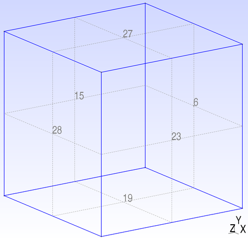
We focus now on how to assign flags in view of the finite element simulation. In particular we aim at "labeling" the boundaries of our computational domain in order to assign boundary conditions. In our example the IDs of the cube surfaces are shown in the figure below:

In order to label boundaries we need to create the so called physical entities. A physical entity can be a point, a line, a surface and a volume. For the example at hand we need to create
- a physical surface with ID 2 which groups surfaces 6, 15, 23, 19, 27, 28
- a physical volume with ID 1 which is volume 1 of the geometry generated
To do that we need to add some additional lines to the cube_geometry.geo script
Physical Surface(3) = { 6, 15, 23, 19, 27, 28 };
Physical Volume(1) = { 1 };
Mesh generation
We want to generate an unstructured tetrahedral mesh of our geometry. The mesh size to be used is h = 0.2. To generate the mesh we open a terminal, we go to the folder wherein the file cube_geometry.geo is located and we launch the following command:
gmsh -3 -clmax 0.2 cube_geometry.geo
The parameter -clmax controls the maximum mesh size of the mesh that we set to 0.2. Please notice that the setting of an appropriate mesh size can be done in other ways different from what we used here (see the documentation of gmsh for detailed instructions about mesh generation). After the command got executed, we obtain the mesh file cube_geometry.msh.
Convert the mesh into the medit format
Finally we need to convert the gmsh mesh cube_geometry.msh into a medit format. To this end we can use the python script gmsh2medit.py. To launch the python script (of course, python has to be installed) we open a terminal, we go to the folder where the file cube_geometry.msh is located and we execute
python gmsh2medit.py cube_geometry.msh cube_geometry.mesh
The first parameter is the name of the input .msh file while the second is the name of the output .mesh file. It is possible to visualize in gmsh the mesh that we have created:

Notice that as alternative to using gmsh2medit.py routine, gmsh provides the possibility to save the mesh directly in medit format, by selecting .mesh when exporting the mesh. Please refer to the documentation of gmsh for detailed instructions about mesh generation. Here you can download the cube_geometry.geo file.
Updated