Wiki
Clone wikiPipsta / Pipsta Circuits
It doesn't always work first time. Let's help our young pioneers by ensuring their first time works first time.
Breadboard prototyping is a great introduction to electronics. It is cheap, reuseable, immediately gratifying and free from the perils of hot soldering irons. It is often a budding electronics enthusiast's first exposure to circuit assembly.
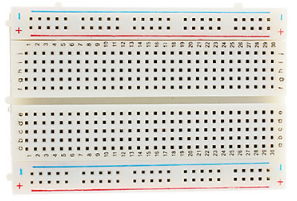
Copying breadboard layouts is traditionally a task of counting rows and columns or playing a kind of "Component Battleships" game ("resistor goes from C2 to H2".) Whilst this is intuitive and –-to a certain extent-- fun, its effectiveness is limited when:
-
component pins land on unindexed points on the top and bottom rails
-
uncertainty arises when placing components in a thicket of already-placed, crooked, neighbouring components
-
'Battleships' row and column referencing can take time
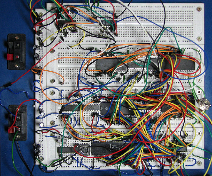
(from https://commons.wikimedia.org/wiki/File:Breadboard_complex.jpg)
Despite best intentions, component orientations often inadvertantly flip through 180 degrees in translation from screen or print to breadboard and eyes get tired in shifting back and forth between source and target. The result of these errors, and even the awareness of the risk of errors, is decreased confidence at a time where students' hearts and minds ought to be won. Remedial action on the breadboard is often fraught and a time-pressured rip-up and repeat is favoured over a difficult inspection of all nodes in the rats'-nest.
If only we could ensure our young pioneers' first time worked first time...
Enter Pipsta and its linerless label media roll. The ability to print high-quality images cheaply and repeatibly onto peel and restick media presents the opportunity to do away with the jeopardy of transcribing from screen or print by simply affixing a precisely scaled layout diagram directly onto the breadboard itself. Circuit assembly is dramatically simplified and sped-up: all component information can be read from the label directly, orientations can be checked as the component is fitted and assembly resolves down to simply pushing the component pins through the target locations on the label into the breadboard below.
A sample breadboard project:
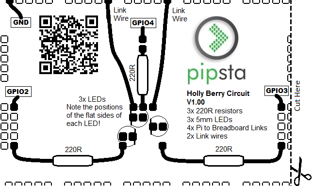
Precise label alignment is conferred by cutting down the centre of the rightmost breadboard column on the label and checking that it is in line with the holes underneath. In practice, this alignment exercise takes just a few seconds and gives perfectly adequate alignment over a 400-point breadboard.
In trials, children as young as 6 years' old (KS1) can assemble circuits with only the minimum of verbal assistance (all images produced with permission):
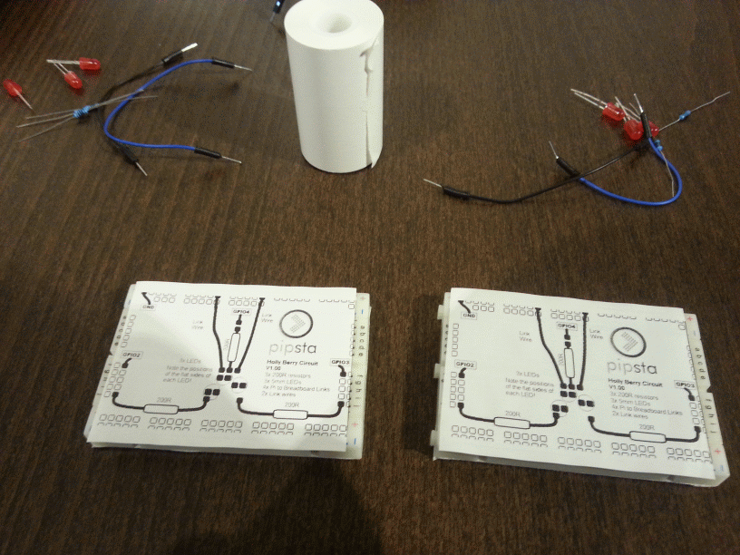 0 minutes – breadboard and kit prepared by adult
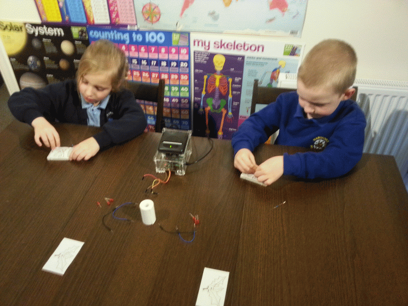 3 minutes – second component being added by KS1 children
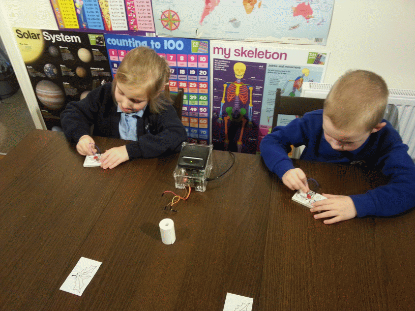 8 minutes – last link wires being added
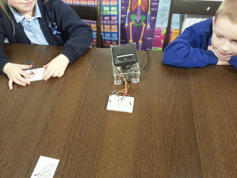 10 minutes – testing circuit on Pipsta (after adult inspection and connection to the Pipsta)
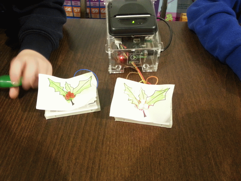 19 minutes – complete with 'presentational layer' coloured-in by the children (adult assistance was required in adding the presentational layer.)
In this 'tame' workshop there were just two children, but neither had been exposed to any electronic components or concepts beforehand. The whole workshop took less than 20 minutes.
Aside from information on which components to select, the only other advice dispensed during the above workshop was:
-
Double-check the flat sides are the right way around
-
Make sure the legs are not bent
-
Push the legs straight down into the breadboard
-
Make sure the legs are pushed all the way down
-
Make sure not to knock any legs out when you put more in
-
Don't worry about the things marked GND, GPIO2, GPIO3, GPIO4 for now
Pipsta Circuits can be produced manually by modification of a bitmap image template (check the Downloads section in the next couple of days!) We also have something in the pipeline which will allow teachers to create their own circuits even more easily. Check the bitbucket next week for the big unveil or follow us on Twitter (@PipstaPrinter) to see the announcement as it happens.
With dramatically improved circuit assembly success rates and times, the pace, scope and easy fault diagnosis of electronics lessons improve. More kids start out with an early STEM victory under their belts, to confidently meet the challenges ahead.
We would love to hear from you! Email us at support@pipsta.co.uk
[END]
Updated