Wiki
Clone wikiFlatCAM / Cutting_the_edges_of_rectangular,_polygonal_or_round_shaped_boards
2. CUTTING THE EDGES OF RECTANGULAR, POLYGONAL OR ROUND SHAPED BOARDS
The purpose of this chapter is to help the Flatcam user with step by step procedures for machining the edges of a board. A rectangular board will be processed first, using the standard Flatcam's Board Cutout function. Next, proceeding a polygonal or round shaped board being a little bit more tricky, an adaptation of the "Isolation Routing" function is necessary to achieve a correct result.
Preliminary note :
In case a tapered end bit is foreseen, refer to V-shaped Bits, Groove Width Calculation and Ready for Use Tables. This page will help to determine the correct value of the "Tool Dia." to type into the corresponding Flatcam boxes.
2.1. Cutting the Edges of a Rectangular Board:
- Flatcam considers that the line generated by the CAD software has no thickness, which isn't true. By default the milling tool will be following the edges of lines drawn by the CAD software instead of their middle. Hence an error equal to half the line width is introduced, placing the machined edge outside the theoretical path or inside it for an internal cavity. The widest line, the largest error.
There are basically, at least, three workarounds:
2.1.1. Approximation with a small error:
- In the CAD software:
- Define an edge line as thin as possible (0.05 mm seems the minimum for the Pcbnew corresponding layer parameter, at least for Kicad ver. BZR4022).
- In addition, set the default line width in the plot parameter box to 0.02 mm. This value seems to be the lower limit of PcbNew (ver. BZR4022, please check it for the newer versions).
- Under Flatcam, proceed with the Gerber as usually done (refer to Flatcam user's manual).
Note that an error of +1/100 mm will remain on the position of every edge.2.1.2. Cheating with the tool diameter under Flatcam, whatever the line width is:
- If its width is unknown, measure it with the micrometer embedded in Flatcam (Menu "Tool", "measurement tool"). The dimensions are located above the status line, under the PCB view pane (fig. 2.10 [1]).
- On the "Gerber Object" tab, under "Board cutout", select a zero margin and a tool diameter slightly smaller than the value that will be used for generating the cutout object then the CNC job and the G-code, finally the milling operation on the CNC. This reduced diameter (Tool dia.) is equal to: dr = tool_diameter - line_width.
- Proceed with the cut-out object creation.
- When done, select the "xxx-cutout" object. Under "Create CNC job", put the normal value of the "Tool Dia." i.e. the "tool_diameter" of the formula above. The result is shown on the following figure on the gap area.
The tool diameter modification shall be done every time a different tool is used.
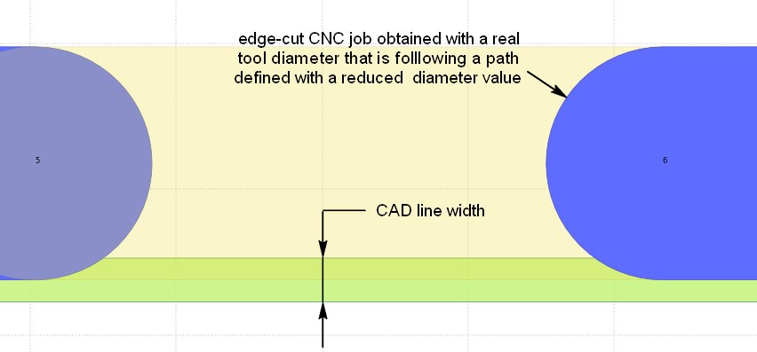
Fig. 2.1 : Gap area showing the edge groove (blue) perfectly following the middle od the CAD contour line (green).
2.1.3. Configuring Flatcam with the CAD software standard line width, whatever the drawing line width is:
- If it is unknown, measure it with the Flatcam's micrometer (see paragraph above).
- Define the correction: subtract half of the line width to the design margin (if any). The margin can be negative in the case the correction is larger than the design margin.
- In this example, the line defining the edge was plotted with a width of 0.15 mm and the tool used for machining the edges was a V-shaped bit giving a 0.736 mm large V-groove. The design margin was 0. Refer to the tool tables [3] for an easy "Tool Dia." determination.
- Open the Gerber object corresponding to the edge cuts (Fig. 2.2).
- Under Board cutout:
- Fill in the margin according to above,
- Configure the tool diameter,
- Launch the geometry generation. The edge of the mill will touch the path defined by the margin. i.d. in case of no defined design margin, the edge will be machined up to the theoretical middle of the drawing line.
Notes: The margin corresponding to the line width correction can be configured as "Application defaults" or "Project Options" under the " Options" tab, "Board cutout", "Margin".
This solution is far better than the two other ones because, once the CAD software output parameters have been frozen it applies to all the boards.
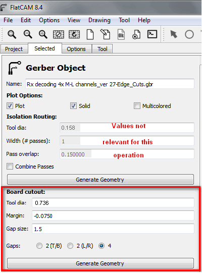
Fig. 2.2 : Configuring properly the location of the edges.
In this case, the edge cut drawing line generated by Pcbnew was 0.15 mm thick
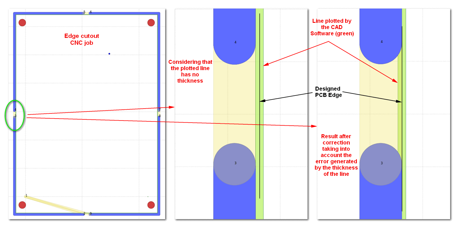
Fig. 2.3 : General aspect of the Edge-Cut. CNC Job and zooms on the detail showing the edge without and with correction.
These results correspond to what would be obtained following the two procedures described above (hugely exaggerated however for the case 1 because the plotted line should be 7.5 times thinner).
2.2. Cutting the Edges of a polygonal or round shaped board:
For the following, it's assumed that a non-discontinuous non-rectangular shape has been drawn around the circuit using the CAD software and that a Gerber file was generated accordingly. For the details concerning the CAD parameters, refer to the above chapter.
Although the Gerber file extracted from the CAD software has the same family name as the Flatcam's conventional edge-cut input file, it needs to be processed in a completely different way. Otherwise, using the "Board Cutout" function, the result will be a rectangle around the board.
Instead, we'll consider it as a copper track, using "isolation routing". Then, selecting the outside only of the path we'll generate the edge-cut file.
The following operations are particularly demanding in terms of accuracy: input parameters, strict order of operations and avoidance of potential errors, for example: forgetting to update the geometry before the next operation.
2.2.1. Inputs:
- CAD drawing line width defining the edges: 'w'. Here Kicad PCBNew ver. BZR4022 has generated the Gerber files with the minimum width of 0.02 mm. We'll use w = 0.02 mm.
- Engraving Tool: V-shaped bit with a flat end. We selected the following:
- Shaft Dia: 3.17 mm
- tip angle: 20 °
- flat end width: 0.2 mm
- Machining depth: 1.6 mm
- The tool tables give a groove width D = 0.764 mm at the surface of the copper.
2.2.2. Creating the path:
- Under Flatcam: Open filename-Edge_Cuts.gbr, double click on the file => the Gerber object pops up.
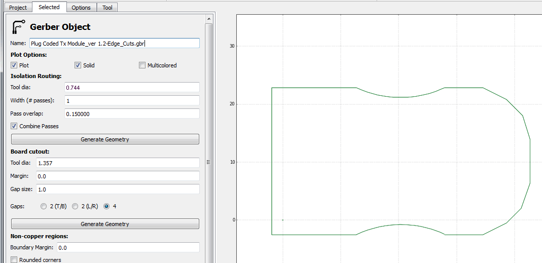
Fig. 2.4 : Gerber image ..
Select:
the tool dia. Here we've to cheat a little bit :
Provided that the drawing line width defining the edge is 'w'
To cut up to the middle of the line, the value to be entered in this field shall be the groove width at the copper surface, obtained with the selected tool dia 'D' minus the line width:
Tool Dia. field value = D - w (here 0.744 mm)
- the number of passes: 1.
- keep the default value for the pass overlap, it won't be used anyway.
- Same for pass combination.
2.2.3. Generate the geometry.
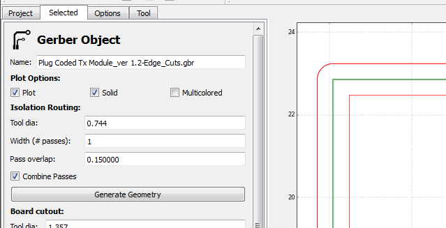
Fig. 2.5 : generated iso object, expanded upper left corner ..
Return under the project tab, deselect the Gerber, select the newly created file: 'name'_Edge_Cuts.gbr_iso
- click on the "edit geometry" icon refer to the figure below), click on the arrow icon to select the shape if not already selected. If the button appearance doesn't want to change, the iso object is probably not selected.
The object is currently materialized by a pair of paths, the inner and the outer ones.
- select the object by clicking close to a corner of the internal path. Both lines turn solid black
- click on the "cut path" icon, both lines turn purple
- click again close to a corner of the inner line, it (only it) turns solid black
- then click on the "delete shape" icon. The inner path turns red.
- click on "Update geometry" to confirm and complete the action. The internal path disappears while the external one turns red.
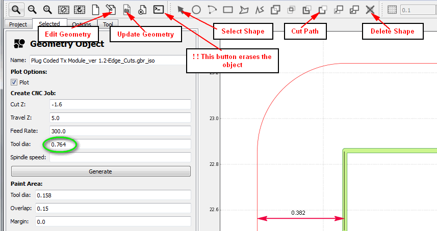
Fig. 2.6 : The internal path has been removed. Note the tool dia on the left pane, that will be used to generate the CNC job then the G-code file. It is exactly twice the distance between the red path and the middle of the green line. ..
Note: It is also possible to perform this operation under the shell command mode. This will be seen further.
2.2.4. Preparing the G-code
- Fill in the boxes under "Create CNC Job:"
- Cut Z: = 1.6 mm (don't forget the minus sign).
- Travel Z: 5 mm (the mill flies at 5 mm above the surface during travel. It can be less but the mill is more exposed to damages).
- Feed rate: (units/mn, eg. mm/mn or ''/mn), depends on the substrate material and the engraving bit characteristics.
- Tool dia: = D = 0.764 mm.
- Spindle Speed: N/A.
- Click on the "Generate" button.
2.2.5. Generating the G-code
- Return to the Project pane, click on the newly .gbr_iso_cnc created object,
- Verify the position of the blue fat line with the "Tool" "measurement tool"
- change the tool dia if necessary and update the plot.
- Then click on Export G-code, name and save it
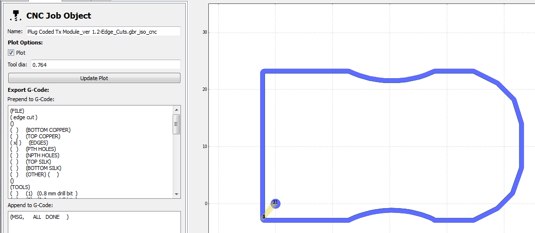
Fig. 2.7 : Here's the result of the CNC job before writing the G-code ..
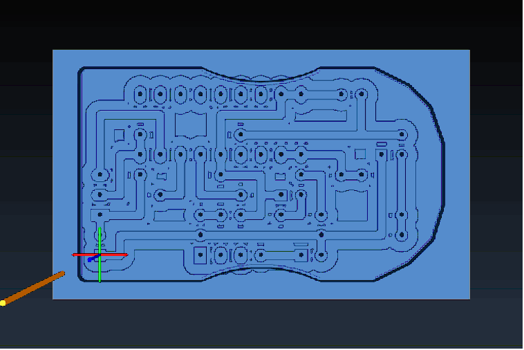
Fig. 2.8 : G-code Simulation Under Camotics [2] This picture shows the board as it should be after machining using the G-code files produced by Flatcam ..
Are you happy with that ? Certainly not !
There's no bridge for attaching the board to the frame. Hence cutting the edges need to be the very last operation because, unless the substrate is stuck to the CNC table with double sided adhesive tape, further machining may really be difficult.
Come back to the iso object. Note that we have kept the visibility of the CAD drawing line to ease the operation.
2.2.6. Creating bridges to attach the board to the frame.
- Edit its geometry again, select the "rectangle" button
- Draw a rectangular shape crossing the external path, where you want the first bridge. The height is not that important but the width shall be equal to the desired gap increased by a value equal to the tool diameter.
- Let assume that we want a 1 mm gap. The tool dia. being D = 0.764 mm (refer to the above), the rectangle will be about 1.75 mm wide.
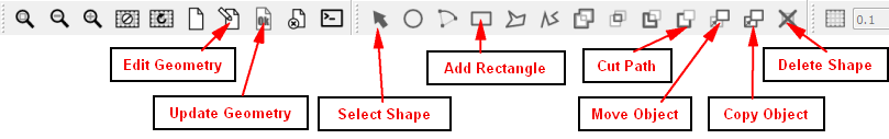
Fig. 2.9 : Position of the buttons used in this paragraph. ..
- The dimensions can be read at the bottom left of the PCB pane (next figure). The value is automatically reset when either mouse button is clicked. Don't move the mouse when the size is correct and press carefully the left button to free the shape, the dashed line turns solid.
- Now, we'll copy this rectangle everywhere a bridge is wanted. Edit again the geometry if necessary.
- Click on the arrow button, select the freshly drawn shape, click on the "Copy Object" button or type "c" on the keyboard. Point again the polygon to be copied and drag the dashed shape to the desired position. Click only once on the mouse otherwise it restarts the copy operation. If so, it will be deleted further on.
- Update the geometry.
- If one of the rectangles is misplaced, select it, type "m" on the keyboard or click on the "Move Object" button, drag it. Don't forget to update the geometry.
- To delete a bad polygon, select it and click on the "Delete Shape" button or type " - " on the keyboard.
| [1] | return to § 2.1.2. |
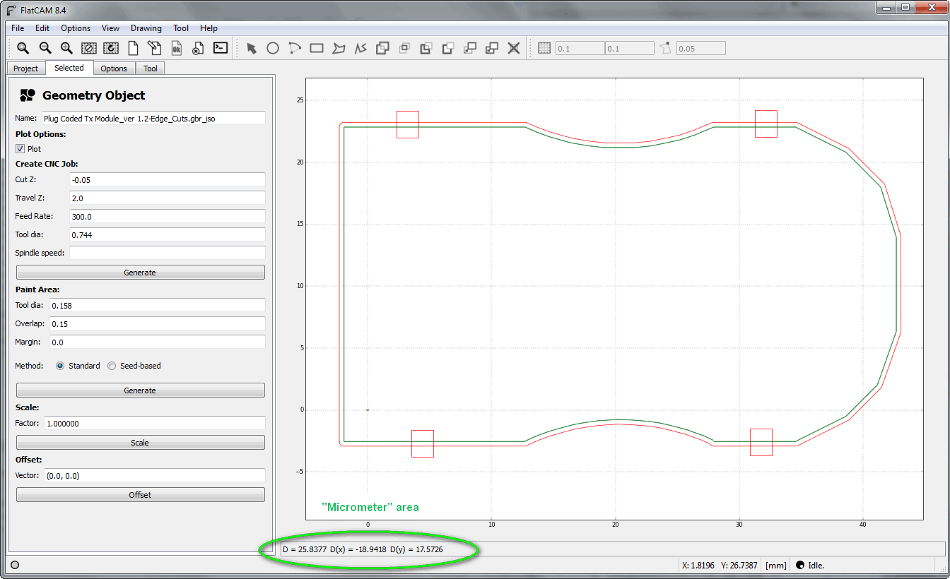
Fig. 2.10 : Outer path with the preselection of the bridge locations
- We are now going to interrupt the external path on the four locations:
- Select "Edit Geometry", hold the "Control" key and select in this order: the external path first then successively the four rectangles. Don't release the control key until the" Cut Path" button has been pressed.
- Update the Geometry. The path appears interrupted inside every rectangle.
- Select again "Edit Geometry", the "Arrow" button, hold the "Control" key, click close to a corner of each rectangle, preferably far away the external path, not to select it. When done, release the key and click on the "Delete Shape" button or type " - " on the keyboard.
- Update the geometry.
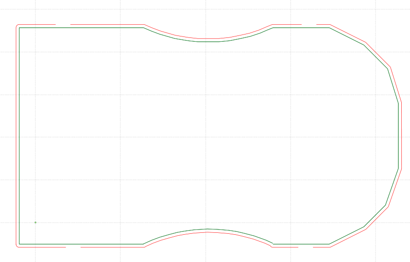
Fig. 2.11 : calibrated path interruptions ..
- Change the tool dia. to the real tool value (here 0.764) and launch the CNC job.
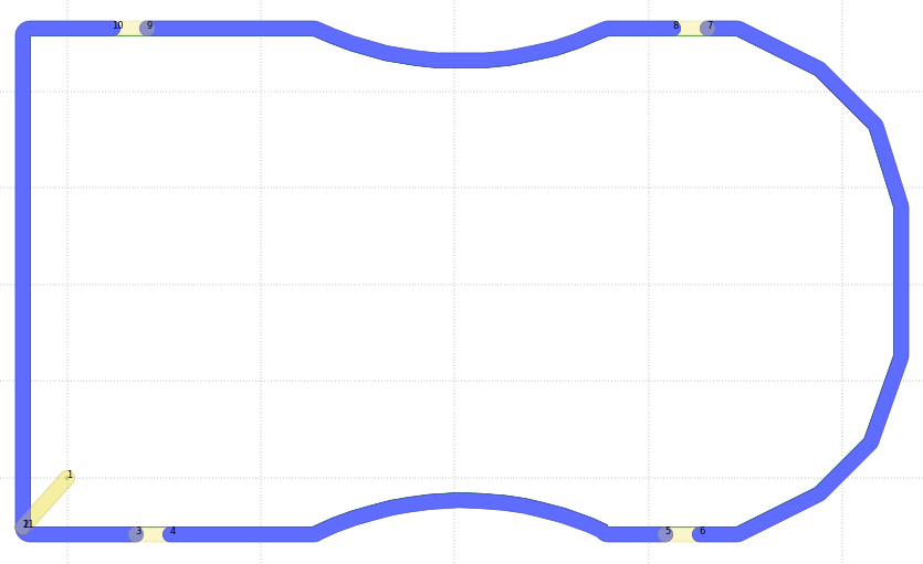
Fig. 2.12 : New edge cutting operation leaving bridges in between the board and the frame for further tooling ..
| [2] | http://camotics.org/ |
| [3] | V-shaped Bits, Groove Width Calculation and Ready for Use Tables |
Click on the flag to return or on the URL to navigate.
If you think that this tutorial may be improved, feel free to drop me a line. Your message will be welcome. Thanks in advance youri.margarin@yandex.ru
Updated