Wiki
Clone wikimofem-joseph / PMMA three point bending
###PMMA three point bending###
Keywords: Crack Propagation, Fracture, High-Order Approximation, Automatic Mesh Refinement
Problem description
A polymethyl methacrylate (PMMA) beam with an inclined slit is examined in a three point bending test as indicated in Figure 1 below. We want to calculate the propagation of the crack from the slit through the PMMA beam. In experiments conducted by Lazarus et al. [2], the authors note that initially the slit is loaded in both tension and out-of-plane shear. As the crack propagates, the crack front gradually twists around the direction of propagation to reach the middle mode I plane of the beam. In the Crack propagation in graphite beam benchmark test, the initial slit is perpendicular to the beam (γ = 90°) and so the crack is loaded in mode I only and propagates straight.

Figure 1. Polymethyl methacrylate (PMMA) beam with inclined slit in three-point bending, from [2].
Files
The different angles of inclination of the slit are assessed, 45°, 60° and 75°. The CUBIT journal files required to generate the model can be downloaded from here:
- PMMA_45degrees.jou (CUBIT journal)
- PMMA_60degrees.jou (CUBIT journal)
- PMMA_75degrees.jou (CUBIT journal)
The files are also located under /mofem_install/mofem/benchmarks/three_point_bending_PMMA/ in the MoFEM source and build directories.
Geometry
Considering the figure above, the dimensions of the PMMA beam are as follows:
L = 260 mm, w = 60 mm, Le = 120 mm, t = 10 mm, a = 20 mm, γ = 45°, 60°, 75°.
Material properties
PMMA is also known as Plexiglas, Lucite and Perspex.
Young's modulus E = 2.8 N/mm²
Poisson's ratio v = 0.38
Griffith energy g = 3.52e-4 N/mm (from [3])
For convenience, the values of E and g above have been scaled by e-3. This is to achieve a Young's modulus close to 1 N/mm² which will simplify the computational performance.
Loads
The reference load, which is scaled, applied to a small area at the top of the beam is equal to 0.048 N/mm².
Finite Element Model
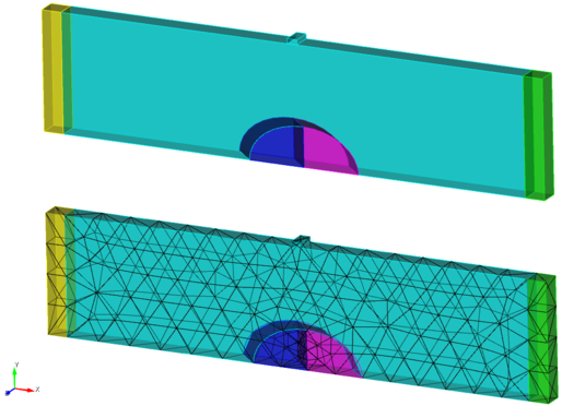
The finite element model consists of a relatively coarse uniform mesh of 4-node tetrahedral elements as shown in Figure 2. We will use automatically different orders of approximation and levels of mesh refinement to improve the solution. In addition to the load shown above, we apply displacement constraints at two edges of the beam to prevent rigid body motions (see CUBIT journal files).
The crack is defined geometrically in CUBIT by a single surface. It is worthwhile to note that the visible cylindrical cutout around the crack is only used to construct the crack geometry and optionally give better mesh control around the crack. The crack tips and crack surface are specified by custom sidesets.

Figure 2. Geometry (left) and mesh (right) for a notch inclined at 45°
Analysis procedure
MoFEM Version 0.2 was used to calculate the results for this problem. The analysis is run in two stages. The first stage uses a script to calculate the Griffith forces for 1st (linear) to 3rd (cubic) order 4-node elements. For each order, analyses with 1 and 2 levels of automatic refinement are run. All analyses were run using 8 processors with the FGMRES (Flexible Generalized Minimal Residual Method) Krylov solver for systems of linear equations and the LU preconditioner. The first script can be executed using:
$ ./convergence_study.sh -f PMMA_45degrees.cub -l -1 -g 3.52e-4 -o 1,2,3 -r 0 -p $NPROC
If desired, the Mode I stress intensity factor ( ) can be calculated directly from the output Griffith forces, see the Analysis procedure section of the plate with horizontal crack benchmark.
The second stage uses a script to calculate, over a prescribed number of steps, the propagation of the crack for a specified approximation order and level of mesh refinement, using the resultant Griffith forces from the first stage. All analyses were run using 8 processors with the FGMRES (Flexible Generalized Minimal Residual Method) Krylov solver for systems of linear equations and the LU preconditioner. To calculate the propagation of the crack for the 2nd (quadratic) order with no levels of automatic mesh refinement, for example, the script can be executed using:
$ ./arc_length.sh -f $DIRNAME/out_spatial_2_0.h5m -a 1 -n 100 -g 3.52e-4 -p $NPROC
Results
The script file required to extract the desired data (from log files) and plot the graphs can be downloaded from here:
The files are also located under benchmarks/three_point_bending_PMMA/ in the MoFEM source and build directories. The graphs can be plotted using:
$ ./plot_graphs_PMMA.sh -o 1,2,3 -r 1,2 -a 45
where -a is angle of inclination of the crack. Log files must be placed into a directory named log_files and log files must follow the naming convention log_ANGLE, with the plot file located one level above log_files. For more information on plotting, see Plotting information.
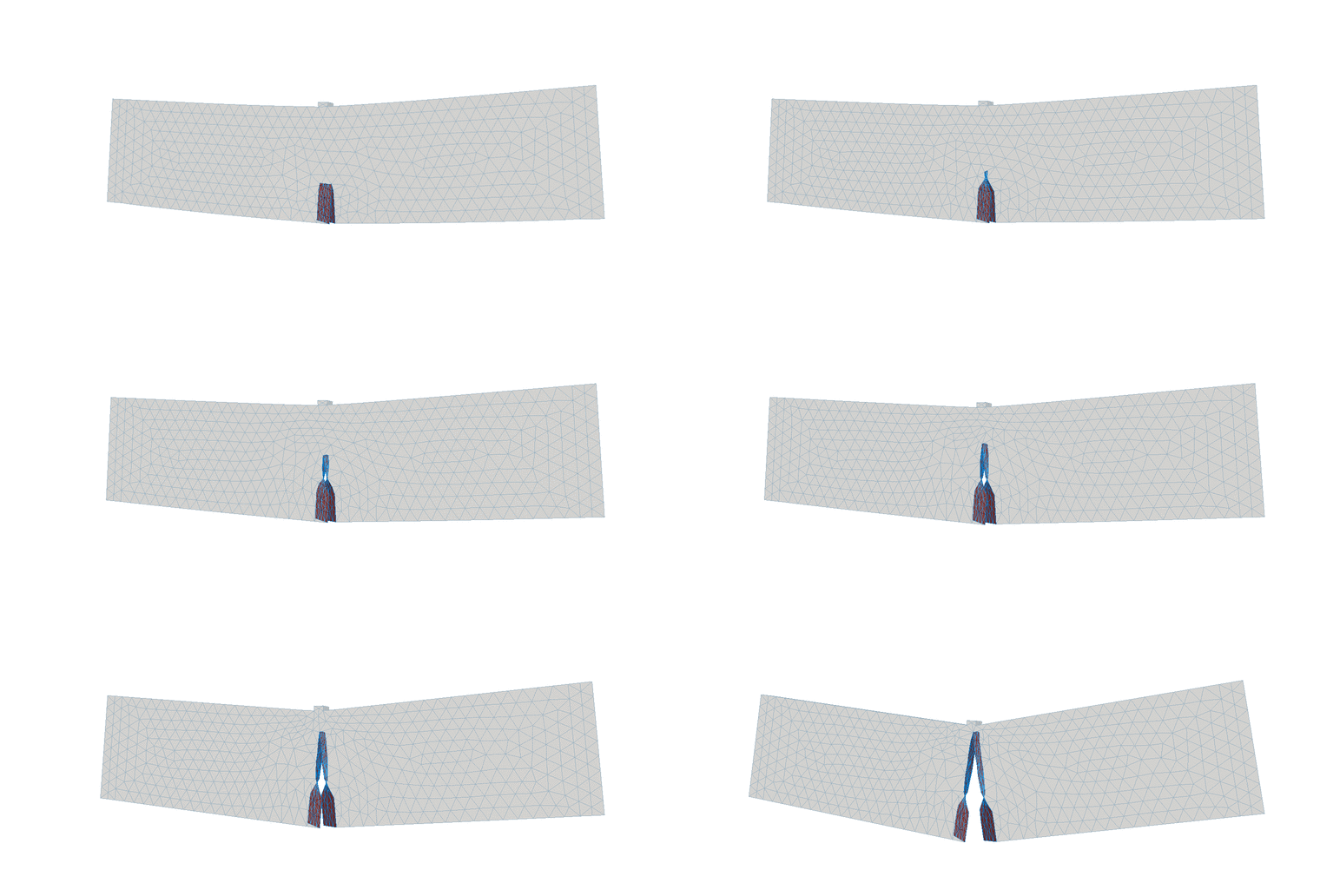
Figures 3, 4 and 5 demonstrate the crack path for second order approximation with no level of mesh refinement for a PMMA beam with initial cracks inclined at 45°, 60° and 75° respectively. Very similar crack paths were observed using first and second order approximations.

Figure 3. Propagation of the crack for a PMMA beam with an initial crack inclined at 45°.

Figure 4. Propagation of the crack for a PMMA beam with an initial crack inclined at 60°.

Figure 5. Propagation of the crack for a PMMA beam with an initial crack inclined at 75°.
Figure 6 shows the stress intensity factors for the first two fracture modes, where d is the half-length of the initial front, and the result from [2]. Four levels of automatic mesh refinement were used to create this graph so as to have several data points along the initial crack.

Figure 6. Stress intensity factors for the initial slit in a PMMA beam with an initial crack inclined at 45°, 60° and 75°, for 4th level of automatic mesh refinement.
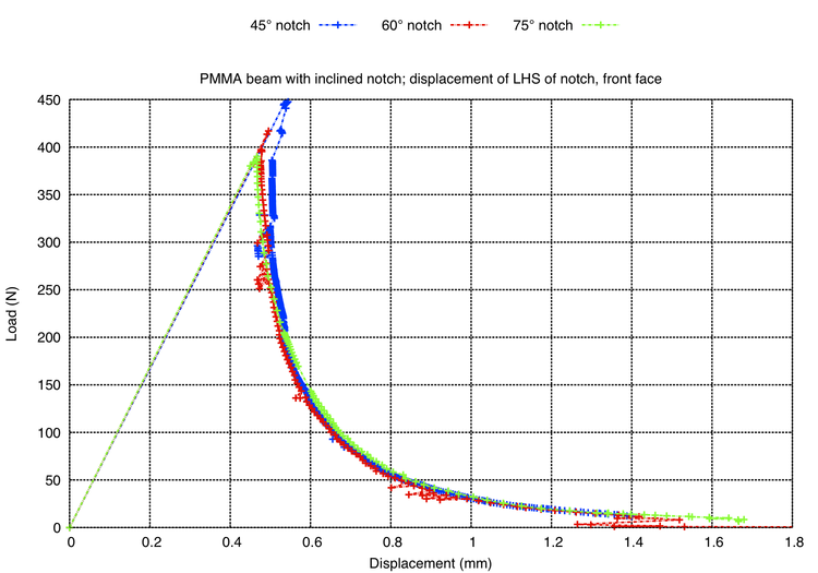
Figure 7 demonstrates the load-displacement response for the node on the front face to the left side of the crack. Clearly, as the angle of inclination of the crack approaches 90°, the ultimate load reduces. The ultimate loads were recorded as 444 kN, 413 kN and 380 kN for 45°, 60° and 75° respectively.

Figure 7. Load-displacement response a PMMA beam with an initial crack inclined at 45°, 60° and 75°.
Table 1 complies the kink angles as found by Lazarus et al. [2] during the experimental procedure, by Pandolfi and Ortiz [3] using the eigenerosion approach and by MoFEM. The angles listed below using MoFEM were obtained during post-processing and are the average of the fton face and back face kink angles.
| γ | Lazarus et al. [2] | Pandolfi & Ortiz [3] | MoFEM | % error to [2] | % error to [3] | |||||||||||||||||||||||||||||||||||||
|---|---|---|---|---|---|---|---|---|---|---|---|---|---|---|---|---|---|---|---|---|---|---|---|---|---|---|---|---|---|---|---|---|---|---|---|---|---|---|---|---|---|---|
| 45° | 61.9° | 57.5° | 66.5° | -7.4% | -15.7% | |||||||||||||||||||||||||||||||||||||
| 60° | 38.4° | 35.5° | 36.1° | 6.0% | -1.7% | |||||||||||||||||||||||||||||||||||||
| 75° | 21.1° | 20.0° | 7.2° | 65.9% | 64.0% |
Table 1. Mixed mode I-III crack growth in three-point bending configuration.
Discussion
Using a very coarse mesh, we have been successful in capturing the twisting of the crack front. The comparison of the results from MoFEM and those from [2] show a good correlation for the initial crack inclined at 45°. However, as the angle increases, the difference between the results from MoFEM and [2] increases. This is attributed to differences in the computational frameworks. Generally, there is little difference in the computed response as the order of approximation increases.
Figure 8 demonstrated the finite element mesh used by Pandolfi and Ortiz [3] for the analysis of the PMMA beam with an initial notch inclined at 45°. Only 1/8th of the beam is modelled, with equivalent boundary conditions applied. The mesh consists of 120,814 nodes and 83,143 10-noded tetrahedral elements. Similar mesh are used to assess the other two angles of inclination. The meshes used in MoFEM, see Figure 2, comprise the whole beam and are very coarse, typically consisting of less than 700 elements, yet we are able to capture the behaviour of the beam accurately. In terms of the kink angles calculated during post-processing MoFEM results, for both notched inclined at 45° and 60°, the calculate kink angle is close to that found experimentally by [2] and numerically by [3].

Figure 8. Mesh used by Pandolfi and Ortiz [3] in the analysis of a PMMA beam with an initial crack inclined at 45°.
References
- Three‐dimensional brittle fracture: configurational‐force‐driven crack propagation, Ł Kaczmarczyk, MM Nezhad, C Pearce, International Journal for Numerical Methods in Engineering 97 (7) 531-550
- Comparison of predictions by mode II and mode III criteria on crack front twisting in three or four point bending experiments, V. Lazarus, F.-G. Buchholz, M. Fulland, J. Wiebesiek, International Journal of Fracture (2008) 153:141-151
- An eigenerosion approach to brittle fracture, A Pandolfi, M Ortiz, International Journal for Numerical Methods in Engineering 92:694-714 (2012)
- Created by Ross Mackenzie
- any difficulties or suggestions email cmatgu@googlegroups.com
Updated