Wiki
Clone wikidsproto_daq / TriggerChronobox
Trigger Overview
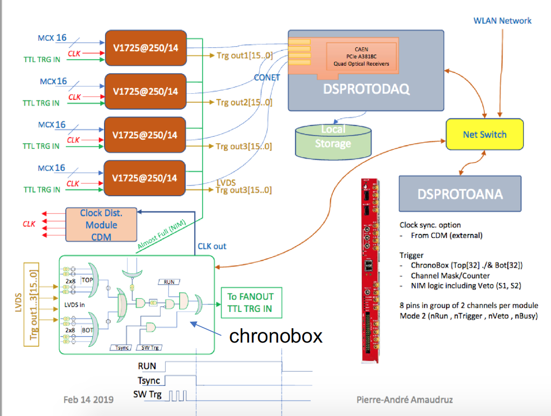
The overview of the PROTO-0 trigger scheme works as follows:
- The V1725s firmware is configured to generate triggers when the digitized waveform goes above or below a given threshold (board configuration is set to 0x10 for triggering on positive pulses and 0x50 for triggering on negative pulses).
- The generated triggers (ganged together in pairs of two channels) are sent out on the ribbon cables to the Chronobox trigger board.
- The chronobox generates triggers based on the V1725 trigger primitives, based on the current configuration.
- The chronobox also inhibits triggers based on the busy state of the V1725s.
This is shown schematically below
Chronobox/Trigger operation during run.
- At the start of a run the chronobox will put out five periodic triggers exactly 200ms apart. These are dummy triggers meant for confirming equipment synchronization and checking baselines. There is actually a pre-trigger from the chronobox which is used to reset all the clocks/counters on the V1725s.
- For each trigger generated by chronobox, the chronobox will send a ZMQ data packet to the ds-proto-daq machine. The timestamp of data packet is used in the V1725 frontend program to ensure that all the equipment has synchronized timestamps.
- The format of the ZMQ data packet is as follows:
Word    Size
----    ---------------
Word 0: unsigned 32-bit | transmit counter, incremented per event sent via ZMQ
Word 1: unsigned 32-bit | Accepted Trigger
Word 2: unsigned 32-bit | Dropped Trigger
Word 3: unsigned 32-bit | low half of 64-bit timestamp
Word 4: unsigned 32-bit | upper half of 64-bit timestamp
Word 5: unsigned 16-bit | Trigger Reason | unsigned 16-bit | Trigger Type
Word 6: unsigned 32-bit | Channel Enable Mask
Word 7: unsigned 32-bit | Channel Trigger Pattern
Word 8: unsigned 32-bit | Channel Assignment Mask
Definitions of the fields are as follows:
- Accepted Trigger - Accepted triggers since start of run, accepted triggers are triggers that were not-suppressed by busy or other means, and were sent out to the V1725s. Reset on start-of-run signal
- Dropped Trigger - Dropped triggers are triggers that were suppressed by busy or other means, and were not sent out to the V1725s. Reset on start-of-run signal
- Timestamp - 125 MHz timestamp of clock ticks since start-of-run. Reset on start-of-run signal
- Trigger Reason - Bits determining whether top and/or bottom 'decision' occurred for trigger. Bit 0 is Bottom Decision, Bit 1 is Top Decision.
- Trigger Type - Reason trigger occurred. Possible values are:
- 0 - None (no trigger)
- 1 - Decision (V1725s caused trigger)
- 2 - External Trigger
- 3 - Internal Trigger (occurs when Test Trigger is fired, or by start-of-run trigger sequence of six triggers)
- Channel Enable Mask - Bitmask of channels that are enabled and be used for decision
- Channel Trigger Pattern - Bitmask of channels that were ON/OFF during trigger decision 8 Channel Assignment Pattern - Bitmask of channels that were assigned to top/bottom. Top = 1, Bottom = 0.
Trigger configuration
Trigger configuration happens in two places:
V1725 trigger configuration
- You need to set the baseline and threshold of the V1725s by changing the ODB variables for the V1725s. There is a page here that allows you to change some of these variables
https://m-darkside.web.cern.ch/?cmd=custom&page=V1725%20Setup
You need to follow the links from that page to set the rest of the ODB values.
Useful Information about V1725 ODB trigger settings (possibly true)
- Post Trigger in 16ns steps
- The trigger threshold (reg 0x1n60) is in DC counts relative to the calculated baseline. The polarity of the trigger threshold is hardcoded to be negative (bit 6 of register 1n64)
- Setting baseline DAC = 1000 sets the digitizer baseline (for 0V baseline) to approximately full scale (~16400 DC counts). Setting DAC = 62000 sets the digitizer baseline to near zero (~400 DC counts)
Chronobox trigger configuration
You set the configuration of the chronobox by going to the chronobox webpage:
https://m-darkside.web.cern.ch/chronobox/
For reference with one V1725 and ChronoBox: V1725 set in TTL Trigger out -> Busy out Trigger in -> ChronoBox Trigger out ChronoBox settings: External Trigger Enable : On External Trigger Invert : OFF Enable/Start Run : ON Invert Channel : 0x0 Enable Channel : 0xFFFFFFFF Channel Assignment : 0xFFFF0000 Invert Busy [0..3] : 0000 Enable Busy Input [0..3] : 1000 Trigger Extend : 3 Invert Trigger Output : OFF Top Min : 1 Top Max : 32 Bot Min : 1 Bot Mac : 32 Decision Type : OR Channel Threshold extend : 0 FPGA Buildtime : 2019-3-20 12:41:03 Run Timestamp: Busy Status (when high trigger rate, it will flicker)
Important parameters are under MOD_TDM, including
- Enable Busy : must only enable busy for channel 0. Will not work if busy is enabled for other channels.
- Channel assignment: defines which channels are in TOP and BOTTOM groups.
- Decision Type: AND means that you require triggers from both the TOP and BOTTOM groups. OR means you require triggers from either the TOP and BOTTOM groups.
- Top min and Bottom min: defines the minimum number of triggers for the bottom and top groups.
- Trigger Extend: the number of 8ns clock cycles that the trigger is extended for. The trigger extend needs to be longer than the digitizer readout time.
- Channel Threshold Extend: the number of 8ns clock cycles that each V1725 trigger is held high for.
Updated