Wiki
Clone wikiXMALab / Rigid Bodies: Settings Dialog
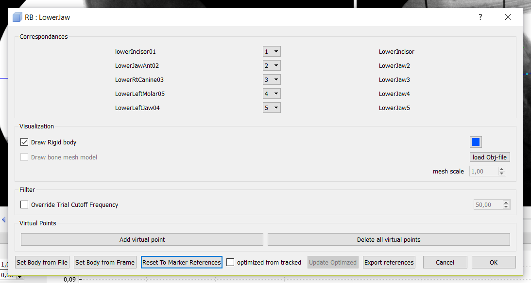
Correspondances
This part tells you which point from the Point window corresponds to which imported CT marker. If these are switched up, you can adjust the number of the point.
Visualization
- "Draw Rigid Body" toggles the visibility of the rigid body.
- The coloured block on the right selects a color.
- "load Obj-file" gives you the option to import the .obj file of the bone that corresponds to the rigid body. See Rigid Bodies: Render Mesh Models.
- "Draw bone mesh model" toggles the visibility of the imported .obj file.
Filter
"Override Trial Cutoff Frequency" toggles the ability to filter the rigid body at a different frequency. This frequency can then be set in the box on the right.
Virtual Points
Set or delete a virtual point that can be used as an artificial marker. See Advanced: Virtual Points
Bottom Buttons
- "Set Body From File" lets you upload CT marker coordinates from a .csv file to set the rigid body. See Rigid Bodies: Create or Import Rigid Bodies.
- "Set Body From Frame" lets you set the rigid body from a certain frame when you don't have CT coordinates. See Advanced: Tracking a Rigid Body without CT coordinates.
- "Reset To Marker References" removes the imported CT coordinates from a .csv.
- "optimized from tracked" toggles the feature that optimizes the imported rigid body with the coordinates of the markers in XMALab. See Advanced: Optimizing Rigid Bodies based on Tracked Data.
- "Update Optimized" updates the optimization.
- "Export References" exports the currently used CT coordinates of the rigid body.
Color of the box in Points window
- Blue: The Points are set manually in the point window and the rigid body is Set from File.
- Green: The Points have been imported as a .csv, so the rigid body carries the associated CT coordinates from the marker.
- Red: No CT coordinates are assigned.
- '+' sign: The coordinates are optimized based on tracked data.
Updated
