Wiki
Clone wikiPipsta / Pipsta Circuits 1 - Holly Berries
Some images below were created by Fritzing. We love Fritzing for its breadboard layouts - please support them!
Difficulty Level


• Step-by-step instructions are provided for the tutor to guide students through a simple electronics workshop
• As with any electronics workshop, the tutor will be expected to diagnose problems with the breadboard implementation, though the complexity of this is significantly reduced with respect to traditional, unlabelled breadboards.
Time to Complete


• The tutor should take time to study the aspects being taught and the depth and direction of the workshop
• The workshop itself can take as little as 20 minutes
• Preparation is recommended in fitting the labels to the breadboards in advance
• Preparation of kits of components is also recommended
• A workshop run for 2x KS1 students took 20 minutes to complete
• Allow approximately 10 minutes for the students to assemble their circuits
• Extra time, proportional to the number of students, will be required for testing (approximately 5 minutes per student)
• Several Pipstas/ Raspberry Pis (and GPIO wires) can be used to reduce testing time
Overview
This tutorial introduces Pipsta Circuits: a breadboard label printing system which simplifies and improves breadboard circuit assembly. See Pipsta Circuits for a discussion on the benefits.
This tutorial provides a step-by-step guide to running a simple workshop introducing electronics to complete beginners. At the end of the workshop, the students will have produced a circuit consisting of 3 independently controlled LEDs, forming a Christmas 'holly berry' display.
Elements of this project are suitable for KS2 children and upwards. Some aspects are relevant only to advanced students.
An example of a student lesson is provided here
Pre-requisites
The tutor will need:
-
A fully assembled and configured Pipsta. There are wiki guides on how to assemble and set-up your Pipsta.
-
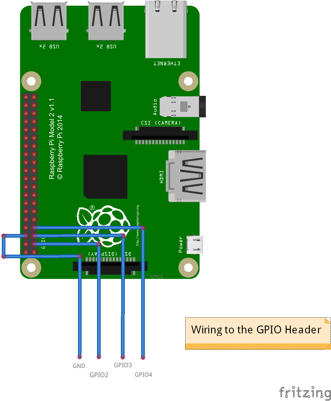
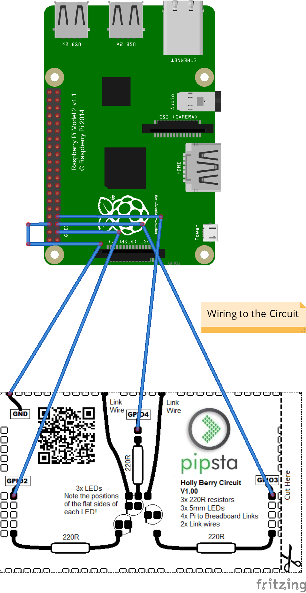
4x GPIO wires (female to male) connected at:
-
GPIO2
-
GPIO3
-
GPIO4
-
GND (ground)
-
-
See, for example, this image of the Raspberry Pi GPIO connector for location information.
-
Connected:
-
Keyboard, mouse and monitor or
-
VNCServer session from PC on the same network as the Pipsta's Raspberry Pi
-
-
Linerless label roll
-
Scissors
For each student in the workshop, you will need:
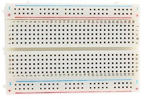
- 400 point breadboard (also known as a "half+ breadboard")
- A Pipsta label printed by running the script print_materials.py (it is recommended that this is printed and fitted to the breadboard before the commencement of the workshop)


-
2x Link wires (male to male) example
-
3x 220 ohm resistors (200 ohm resistors are also acceptable)
-
3x 5mm red LEDs
-
Green felt-tip pen (optional)
Step-by-Step Guide
1) If you haven't done so already, create a new directory under '/home/pi/pipsta/Examples' called 'christmas',
2) Download the file '6_HollyBerries.zip' from here to the 'christmas' directory,
3) Right-click the file and select 'Extract Here'
4) You should now see:
• File: print_materials.py - the first script for this project
• File: led_berries.py - the second script for this project
• File: berry_cct.png - the first image used for the project
• File: holly.png - the second image used for the project
• Directory: image_print - the module used to print the images.
Preparation
1) Print off sufficient labels for each workshop student by navigating to the directory:
/home/pi/pipsta/Examples/14_Christmas/6_HollyBerries
...and pressing [F4] to bring up the terminal before entering:
#!python

python print_materials.py
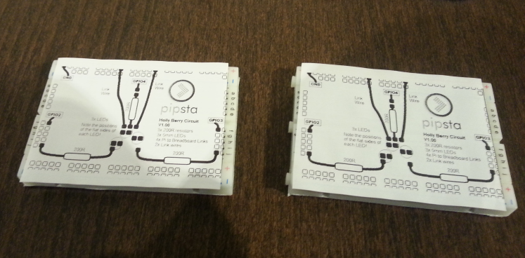
2) For each label: Cut precisely along the dashed line of the label
3) For each label: Fit the label to the breadboard, ensuring it is square by checking the alignment with the last column of holes
4) Fit the GPIO wires to the Pipsta/Raspberry Pi. If you are using the Pipsta:
-
Lift the printer out of the top plastics and lay it to one side. You do not need to disconnect the wires
-
Taking heed of the orientation of the GPIO connector, fit the GPIO wires to the Raspberry Pi's pin header:
-
Bring the wires out through the front aperture of the Pipsta housing
-
You may wish to make a note of the colour sequence of the wires or label the unconnected ends
-
Replace the printer in the top plastics.
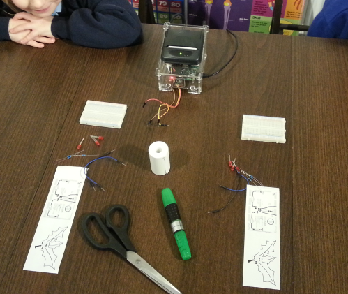
5) Gather the components into kits
Workshop
Assembly
1) The students are introduced to resistors (blue or beige, two legs), LEDs (red, round, two legs) and link wires. Each component's target location is pointed out (resistors are loosely rectangular, LEDs are loosely circular) in sequence during the assembly .
2) Preparatory advice is given on assembling the circuit, namely:
-
Double-check the flat sides are the right way around
-
Make sure the legs are not bent
-
Push the legs straight down into the breadboard
-
Make sure the legs are pushed all the way down
-
Make sure not to knock any legs out when you put more in
-
Don't worry about the things marked GND, GPIO2, GPIO3, GPIO4 for now
3) The students are asked to assemble the circuit. Allow a maximum of 10 minutes.
4) The tutor should now inspect the circuits. Look for:
-
Completion of circuit
-
Errors in component location
-
Components not pressed all the way home
-
Shorted components (though this is intentionally minimised by the layout)
-
LED orientations
5) Resolve any evident faults
Testing
1) After any remedial aspects have been addressed, the tutor should connect each breadboard in turn to the Pipsta/Raspberry Pi:
2) The tutor should now run the script led_berries.py. Note that this should be run with Super User privilege to allow access to the GPIO port:
#!python

sudo python led_berries.py
3) The LEDs will light according to the sequence described in the script (see How It Works below for more information). If some of the LEDs are not lighting, the most likely faults are:
-
(if none of the LEDs are lit) GND is not connected correctly
-
(if some of the LEDs are lit) Some LEDs are not oriented correctly
-
Wires/legs have come loose during assembly
4) If all the LEDs illuminate at various stages, the student has assembled the circuit correctly. If you notice an error in the sequence, check you (the tutor) have connected the GPIO lines correctly!
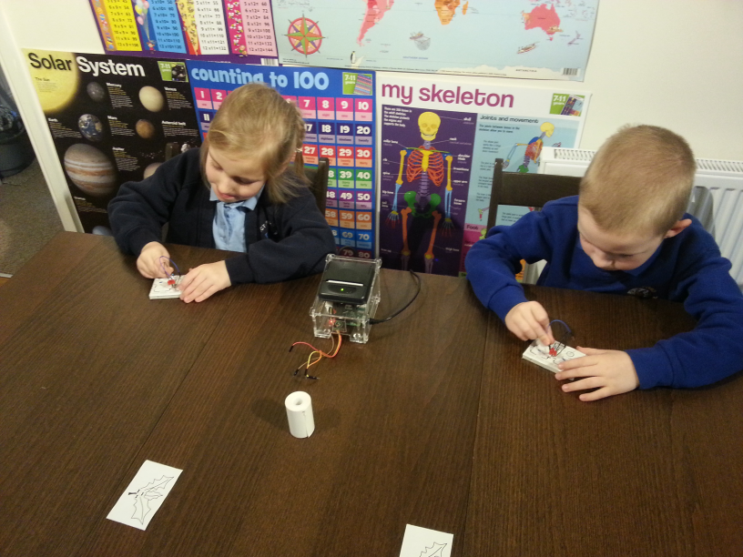
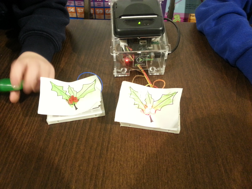
5) Younger students can then colour the 'presentational layer'. It is recommended that the tutor help younger students fit this layer over the top of the existing circuit to cite the LEDs correctly.
How It Works
Holly Berry Circuit
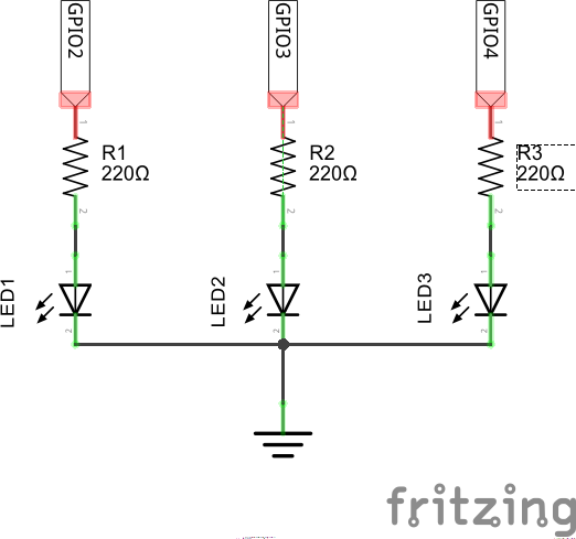
The detail in points 1-10 below is suitable as an introduction to students with little or no electronics experience. Points 11-13 are suitable as an extension to this knowledge, and is intended for intermediate students.
1) A GPIO line, when set 'high' or 'on', allows current to flow through the resistor and LED and into the GND (ground) pin ('low'). In our circuit, when we set a GPIO line to '1', the GPIO voltage will be 'high'/'on', causing current to flow through the LED and the LED to light.
2) No current will flow from one pin to another pin at the same 'voltage': in this case 'high' to 'high' or 'low' to 'low'.
3) A 'resistor' resists the flow of current down the branch of the circuit it is on, making less current flow than if it was replaced with a wire.
4) The resistor values have been chosen to 'set' the correct current flowing through the LEDs. The manufacturers of the LED tell us what this current should be.
5) The lower the resistance, the more current will flow and the brighter the LED. Reducing the resistance below 220 ohms is not recommended for reasons explained below (but basically it could cause damage to the Raspberry Pi.)
6) Increasing the resistance will cause less current to flow. Increasing the resistance will eventually mean the LED will not illuminate. It is safe to try increasing the resistance if you want to investigate this.
7) The appropriate current is highly dependant on the type of LED used. Don't expect all LEDs to work or light as brightly using the same circuit.
8) So-called 'Conventional Current' flows from the the higher voltage side (in this case the GPIO pin when it is 'high' or 'on') to the lower voltage side (in this case the ground pin.)
9) LED stands for "Light Emitting Diode". A diode allows current to flow in one direction only, meaning that --if you fit the LED the wrong way around-- current will not flow (and the LED will not illuminate.)
10) LEDs need to have a minimum voltage applied to them to work. This can be as low as 1.8 volts for red LEDs, but can be more than 3 volts for blue LEDs.
11) For Intermediate Students: We have used the terms, voltage, current and resistance in this workshop. These have the following units:
-
Voltage - volts
-
Current - amps (more commonly milliamps for microelectronics and breadboard projects)
-
Resistance - ohms
12) For Intermediate Students: There is a relationship between voltage, current and amps called Ohm's Law, which takes this form:
Voltage = Current x Resistance
...and can be re-arranged to give:
Current = Volts ÷ Resistance
...and:
Resistance = Volts ÷ Current
13) For Intermediate Students: The GPIO pins, when 'high' are at 3.3volts. Typical red LEDs need a minimum of about 1.7volts and have a recommended current of 20milliamps (20 thousandths of an amp)
so,
3.3volts - 1.7volts = 1.6volts
This 1.6 volts is then used to choose a resistor to set the current flowing into the LED. Using Ohm's Law:
Resistance = Volts ÷ Current
...so
Resistance = 1.6 ÷ 0.02 = 80 ohms
It can therefore be seen that, to set the current to 20milliamps, we should use an 80 ohm resistor.
Why are we using 220 ohm resistors?
There are a few considerations here. Some or all of these are considerations for an Electronics hobbyist, so --if you are learning Electronics-- it is certainly worth working through these in detail.
1) Firstly, 80 ohms is not a commonly available value of resistor: Resistors are not made in every possible value, but in what is called E Series values. It is the job of the person designing the electronic circuit to pick a component with a resistance value close to the calculated resistance. Sometimes this should be a nearby higher value, sometimes a lower value, depending on whether you have calculated a minimum or maximum resistance for your circuit. See here for more information on E-Series resistance values. 220 ohms is in the very commonly available E6 Series as it is a multiple of 22. This is not justification enough though, as it can be seen that 100 ohms and 150 ohms are also in this E6 Series and are evidently much closer to the 80 ohm theoretical figure. Moving to the E12 series even gives an 82 ohm resistor value. Let's look at some of the other considerations then!
2) Resistors have a tolerance, quoted as a percentage: For 5% tolerance resistors, the actual resistance could be up to 5% more or 5% less. At 5%, our nominal 80 ohm resistor could be as low as 76 ohms or as high as 84ohms. Because we don't want to draw more than 20milliamps, we need to select a resistor that would guarantee we do not dip below 80ohms. At 5%, 100 ohms would be better, as this is a standard E6 Series resistor and would give a resistance in the range 95ohms to 105ohms.
3) The Raspberry Pi has an absolute maximum, total current allowance of 50milliamps for the GPIO port: It can be seen that 3 lots of 20milliamps would exceed this. For that reason, we need to draw less current, and therefore use higher value resistors. Before we rush off to calculate the required resistance for 50 ÷ 3 = 16.7milliamps, there is one very important thing to consider...
4) We don't know what your power arrangement is: The power for your circuit is ulimately drawn from your Raspberry Pi power supply, and this could be 2A, 1A or even less if you are using --say-- a standard USB phone 'charger'. The Raspberry Pi itself can draw several hundreds of milliamps. Added to this, we don't know what else is drawing current from your Raspberry Pi: you might have a power-hungry wireless keyboard, wireless mouse and USB Wi-Fi dongle attached. As we cannot speculate what the current into or out of your Raspberry Pi will be we are playing it safe!.
Note: It is worth looking for signs of power drop-out on the Pi. If the red LED on the front of the A+, B+ or Pi2 B is not constantly lit (perhaps flickering), you may want to consider an alternative, higher current USB power supply.
5) They're 'bright enough'(!): At 220ohms, we can use Ohm's Law to calculate a current of:
Current = 1.6 ÷ 220 = 7.2milliamps
The LEDs are still illuminated well enough at this current to be perfectly visible in a well lit office or classroom. If you were considering use in bright sunlit outdoors applications, you may want to reconsider this stance. The above considerations would help you to decide an alternative.
print_materials.py
This is essentially a variant of the standard image_print.py which:
1) Opens berry_cct.png
2) Rotates it so it runs down the lenght of the label roll
3) Prints the image
4) Opens holly.png
5) Rotates it so it runs down the lenght of the label roll
6) Prints the image
7) Feeds the label image to the tear point
Note that this script makes no attempt to scale the image: the image MUST be 384 dots wide to suit the available print width!
led_berries.py
This Python script has intentionally been kept simple: there are more 'Pythonic' ways of implementing this, but these detract from ease of understanding. Depending on the scope of the workshop being provided, this may or may not be exposed to the students.
1) The script uses two imports:
-
time - this is used for delays in the script
-
RPi.GPIO - this gives access to the GPIO pins
2) Skipping past the definitions of pattern_strings and SLEEP_TIME for a moment, we can see several lines beginning with 'GPIO'.
3) GPIO.setmode() takes the value GPIO.BCM. BCM stands for 'Broadcom' one of the two possible numbering schemes. One relates to the pin numbers of the connector itself, the other relating to GPIO (General Purpose In/Out) lines. The choice is arbitrary but they should never be confused; we will be using BCM for this project.
4) The next 3 lines set each of the GPIO lines to be outputs. This is necessary for us to be able to put high and low voltages onto these pins of our circuit.
5) The code wrapped in a 'Try' block loops forever (until the program is exited by CTRL-Z).
6) The line:
#!python

for pattern in pattern_strings:
...loops through all of the lines in the pattern strings[]. In this list of strings, each character defines the state of the GPIO Line:
7) The first, second and third characters map to GPIO2, GPIO3 and GPIO4 respectively. This is handled in the three 'if...else' blocks in the code that check whether characters [0], [1] and [2] are '1' or not, and set the corresponding GPIO lines accordingly.
8) a '1' means that line is high, a '0' means that line is low. For our circuit, when a GPIO line is '1', its corresponding LED is 'on'. Conversely, a GPIO line at '0' will mean the LED is 'off'.
9) It can be seen that -- for the first 6 lines of pattern_strings[]-- all lines are high.
10) For the next six lines of patterns_strings[]:
-
The lines are all low initially (so all LEDs are off)
-
GPIO4 goes high, so a single LED illuminates
-
GPIO4 and GPIO3 are then both high, so two LEDs illuminate
-
GPIO4, GPIO3 and GPIO2 are then all high, causing all LEDs to illuminate
-
The next two lines repeat two of the previous patterns, and the number of illuminated LEDs will correspondingly decrease to 2 and then 1 again
11) The next 6 lines illuminate a single LED at a time, with each LED illuminating in turn
12) In the final 6 lines all LEDs are alternately on then off
13) Note that, at the end of the for loop, a delay is called by:
#!python


time.sleep(SLEEP_TIME)
...where SLEEP_TIME = 0.25, which is a quarter of a second. This figure has been chosen to allow each of the states to be observed, without the pace being too slow and boring!
14) Note that once all patterns in pattern_strings[] have been shown, the while True will be executed again, effectively reseting the count and walking through the sequence again and again forever.
15) The last two lines of the script:
#!python


except:
    GPIO.cleanup()
...are provided to catch exceptions and revert the GPIO lines to their default states in the event of such an exception. Pressing CTRL-Z is actually considered to be an exception, so this will 'clean-up' the GPIO lines in preparation for future scripts that may be run.
16) Note that the lower two LEDs actually remain somewhat dimly on after the end of the program. This is actually an interesting consequence of GPIO2 and GPIO3 having other, alternative functions which mean that they have internal resistors pulling them up to a high state by default, even if this peripheral is not enabled. These lines are used for a communications interface called I2C. A description of this is beyond the scope of this tutorial. If this were to be a problem in other circuits you design, it is recommended that you pick other GPIO lines without alternative functions. Again, see here for more information on the other pin functions.
Feedback
We would love to hear back from you about this and any other Pipsta projects. Please drop us a line at support@pipsta.co.uk
[END]
Updated