Wiki
Clone wikiPipsta / Pipsta Circuits Template and Script
Difficulty Level


• No Linux or Raspberry Pi knowledge is required,
• A fully assembled and set-up Pipsta and an internet connection are required,
• You will need to be competent at breadboard circuit design to modify the template and avoid damage to your Pi and components.
Time to Complete


• The tutorial covers the operation of the script in overview.
• You should allow yourself plenty of time to lay-out and test your circuit.
Overview
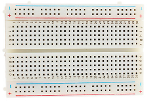
This project comes with a breadboard template for you to modify in the graphics editor of your choice (be it Paint, GIMP etc.)
Once the template has been modified, the circuit can be printed using the accompanying script.
This method of creating Pipsta Circuits is more labour intensive than using the Fritzing script (see here for details), but it can deliver decluttered, non-isometric layouts.
Pre-requisites
-
This project assumes you have a fully working and configured Pipsta. There are wiki guides on how to assemble and set-up your Pipsta.
-
You will also need:
-
A graphics editing program
-
A 'Half+Breadboard'

-
Components to test your layout
-
Scissors will be needed.
Step-by-Step Guide
1) If you haven't done so already, create a new directory under '/home/pi/pipsta/Examples' called 'christmas',
2) Download the file '12_PipstaCircuitsTemplate.zip' from here to the 'christmas' directory,
3) Right-click the file and select 'Extract Here'
4) You should now see:
• File: print_materials.py - the script to print the Pipsta Circuit
• File: pipsta_breadboard.png - the template image
• File: snip.png - the graphic used to show the user where to cut
• Directory: image_print - the module that does the printing
5) Run the print materials script:
#!python

python print_materials.py
6) A blank breadboard image should be printed. Feed this out past the tearbar and cut along the dashed lines with scissors.
7) Affix the Pipsta Circuits label to your half+breadboard.
8) Confirm the extents of the board have good alignment by pressing a component leg through the label and into the breadboard underneath.
9) Now copy the breadboard image to another filename and/or location and edit it using your graphics editor of choice.
10) Tips for editing:
-
Fill-in the target terminals to avoid ambiguity
-
Remove all unnecessary terminals except those around the periphery and especially ensure that the terminals that have been sliced in half are NOT removed: these are vital for correct alignment of the label to the breadboard and hence the accuracy of component positions when pressed through the label thereafter.
-
Try to keep 'dangerous' signals/voltages apart. Keep voltage rails well away from one-another and make sure that 'excess' component legs cannot short on adjacent components
-
Try to make your symbols unambiguous
-
Try to keep logos and legends close to the components to which they refer
11) Here are some example layouts for reference:


How It Works
The script is fundamentally no different to that used in previous Pipsta Circuits tutorials, albeit with a snip image applied separately.
Feedback
We hope you have fun with this project, and would love to hear back from you about this and any other Pipsta projects. Please drop us a line at support@pipsta.co.uk
[END]
Updated