Wiki
Clone wikiPipsta / Fritzing Alpha to Pipsta Hack
Difficulty Level


• No Linux or Raspberry Pi knowledge is required,
• A fully assembled and set-up Pipsta and an internet connection are required,
• This is a 'hack', i.e. is not a very robust system, and is based on an alpha release (0.6.3 [Qt4.8.1]) of the Fritzing application for the Raspberry Pi. If the release version of the Fritzing application, or the underlying Qt changes there is every chance that the methods and scripts used will no longer work. If you accept these limitations, the experience should be straightforward and the difficulty level should be low!
Time to Complete


• The tutorial covers the operation of the script in overview.
• The tutorial is fairly open-ended as it encourages tinkering with breadboard layouts!
Overview
The Holly Berries and Rudolph projects are low-risk projects for beginners in electronics to learn about the basics of voltage, current and resistance and the use of breadboards. However, the images for the layouts themselves are fairly labourious to prepare, and are hand-crafted in image editing programs. The introduction of new types of components requires the creation of new 'foot-prints', and wires must be manually drawn-in. It is hoped(!) that this makes for clear, unambiguous, self-contained projects, and we will be releasing more projects like this in future.
However it has become clear that many would like to create their own simple breadboard layouts and print these out using the Pipsta Circuits system. For these people, we have a system which uses Fritzing, a self-contained, downloadable schematic, PCB and breadboard layout application.
Fritzing for the Raspberry Pi is in alpha, and there are limitations to its use. It does, however, allow breadboard circuits to be laid-out, and have a good-sized library of components to play with. Importantly, it also provides a File Export to PNG format: ripe for a Pipsta Python script to read-in, resize, crop and print-out on a 1:1 breadboard scale.
Users can therefore use this to design their own circuits, print them out, stick them to breadboards and gain all the benefits of Pipsta Circuits, namely:
• Cheap and easy to replicate allowing bigger groups of students and/or younger students to participate
• Quicker to assemble than standard breadboard as no cross-referencing
• Lower risk in assembly
• Easier debugging when things do go wrong - pin positions versus targets are much more easy to check than for busy breadboards obscured by components and wires at all angles.
This project will take you through the full process, from installing the required components, to printing your first Fritzing breadboard layout on the Pipsta.
Pre-requisites
-
This project assumes you have a fully working and configured Pipsta. There are wiki guides on how to assemble and set-up your Pipsta.
-
A Full-sized Breadboard
In a departure from the previous Pipsta Circuits Tutorials, this project is only suited to a full-sized breadboard:

...as opposed to the half+breadboard:

Apart from the obvious size differences, the upshot of this is that the rails at the top and bottom will be offset by half a hole-pitch, meaning that --if you attempt to use the label on a half+breadboard, the pins will not press through their targets, and will need to be offset by half a hole.
- Scissors will be needed.
Step-by-Step Guide
1) If you haven't done so already, create a new directory under '/home/pi/pipsta/Examples' called 'christmas',
2) Download the file '9_FritzingToPipstaHack.zip' from here to the 'christmas' directory,
3) Right-click the file and select 'Extract Here'
4) You should now see:
• File: fritzing2pipsta.py - the script for this project
• File: attribution.png - the ''header' and attribution image for the image produced
• File: snip.png - the 'footer' for the image produced
• Directory: image_print - the module that does the printing
5) Now install fritzing with:
#!python

sudo apt-get install fritzing
6) This will install the alpha version of Fritzing to the Pi.
7) Once complete, on the XWindows desktop, click the 'Menu' button and move to 'Programming'. You should see the Fritzing application is now installed:
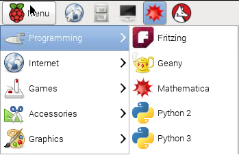
8) Launch Fritzing. You will see an error as it opens:

...let's accept this for now. Once the application has loaded, you should be presented with the breadboard editor screen:

9) IMPORTANT: Before continuing, you must drag the breadboard to the top left corner of the design space. By this, we mean that, with the horizontal slider at the far left hand side, and the vertical slider at the very top, the breadboard is located at the top corner. Failure to do this can cause the Pipsta script to fail later on! If you think this may get onerous (and it may), save the file after doing this, and use this as a template for future work.
10) Drag an LED from the tray on the right window, into the design area:
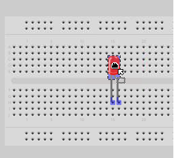
11) The legs of the components should snap to the breadboard pins when dropped there. Additionally, connection information is shown in the green 'glow' down the breadboard's underlying conductors:
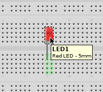
12) Next drag and drop a resistor onto the breadboard area as shown below:
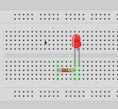
13) Now scroll down the list of components in the tray until you find the following connector:
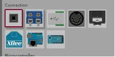
14) Drag this onto the design. You will notice that this is actually a 2-way connector. In this version of Fritzing, modifications cannot be made to the number of ways (hence the warning dialog we dismissed earlier.) For the purposes of this tutorial, we will cheat:
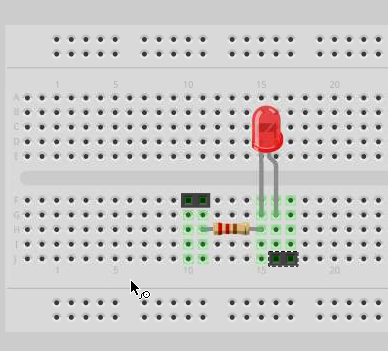
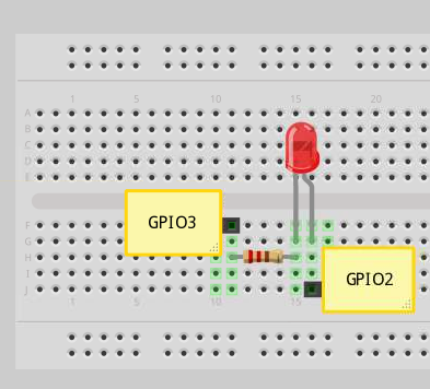
15) Down at the bottom of the component tray, you will find a 'note' symbol. Drag two of these onto the breadboard area to 'conceal' the redundant pins:

16) There is a little drag tool at the bottom right of each note that allows them to be resized. At the end of the process, you should have something like this:
17) Whilst we're introducing notes, add notes for the resistor (value) and LED:
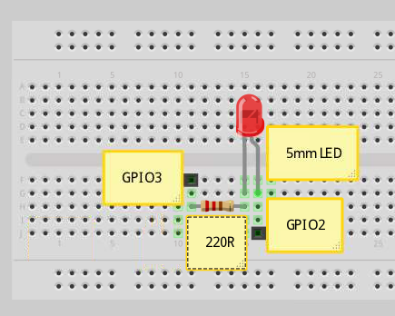
18) We could use this exactly as it is, but let's make one last modification to the circuit to counter some of the disadvantages of the isometric view on that LED.
19) Carefully select the bottom of one of the resistor legs, and drag it up towards the red dome. This may take some careful picking and --if you end up with a blue 'wire' drawn over the top, press CTRL-Z to undo this and try again. You should end up with something like this:

20) Do the same for the other leg:

21) Now drag the LED down so the pins are in their former position:
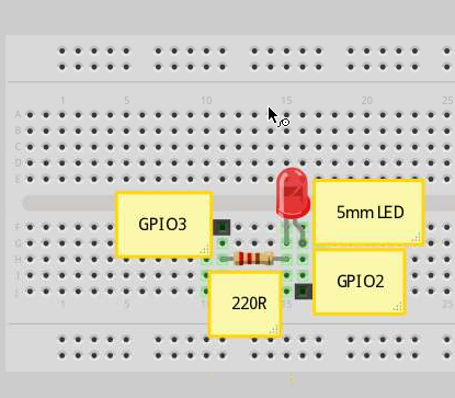
22) This at least liberates some of the tracks above the LED for other components and wiring.
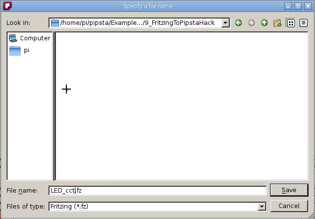
23) From the menu: File>Save, and save your design as "LED_cct.fz"
24) From the menu:
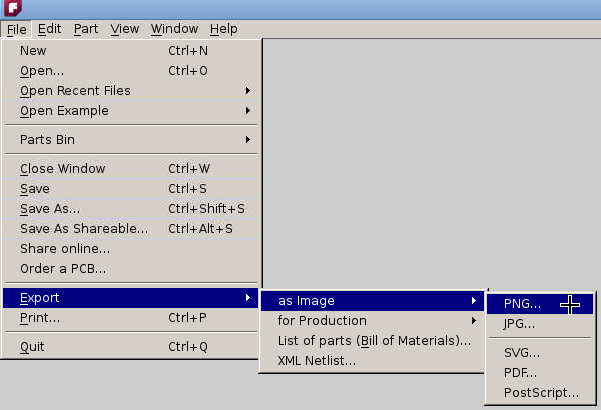
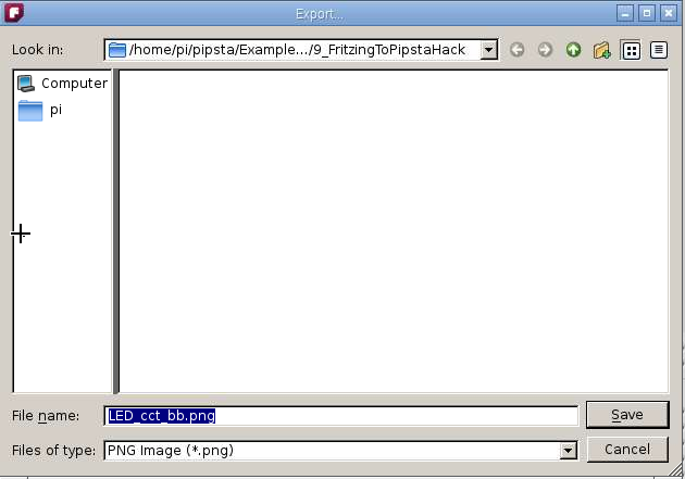
25) Save the file as the default "LED_cct_bb.png":
26) Minimise Fritzing and navigate to '/home/pi/pipsta/Examples/christmas/9_FritzingToPipstaHack', press F4 to bring up the terminal.
27) In the terminal, type:
#!python

python fritzing2pipsta.py 'LED_cct_bb.png'
28) This will now print the Pipsta Circuits label.
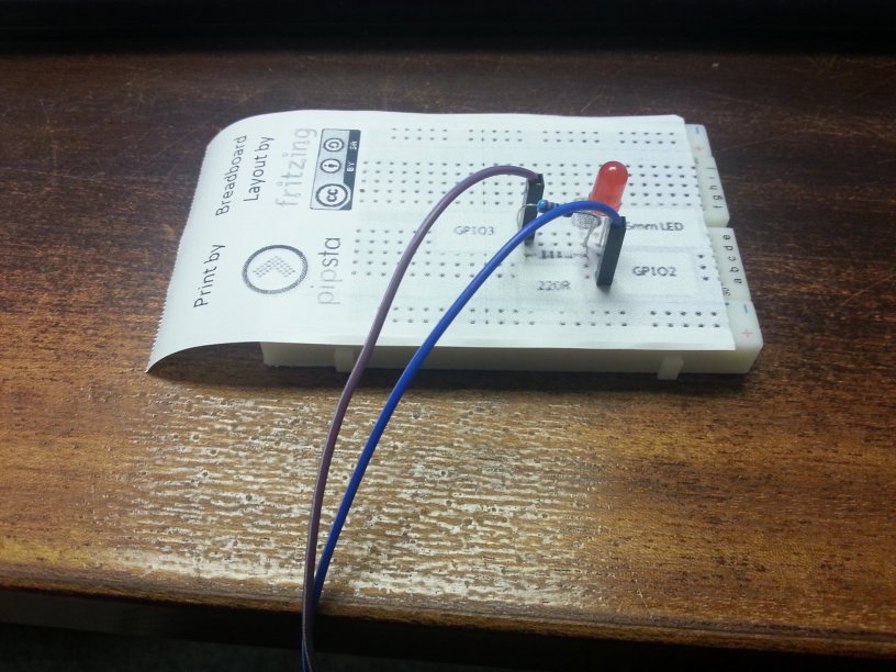
29) Cut this down the dashed line and apply to your breadboard
30) With only Half+Breadboards around, we have had to make a more dramatic cut to our label, but you can see the principle:
How It Works
1) Fritzing exports a PNG file
2) The fritzing2ipipsta.py script:
-
Crops the Fritzing information from the bottom of the PNG (but don't worry)
-
Crops all whitespace from around the breadboard outline
-
Resizes the breadboard image to be 1:1 with a real breadboard
-
Prints the attribution header, the modified PNG image and a graphic showing where to trim
-
Feeds the whole label to the tear bar point
Feedback
We hope you have fun with this project, and would love to hear back from you about this and any other Pipsta projects. Please drop us a line at support@pipsta.co.uk
[END]
Updated