Wiki
Clone wikiPipsta / Pipsta Circuits 2 - Rudolph
Some images below were created by Fritzing. We love Fritzing for its breadboard layouts - please support them!
Difficulty Level


• Step-by-step instructions are provided for the tutor to guide students through a simple electronics workshop
• As with any electronics workshop, the tutor will be expected to diagnose problems with the breadboard implementation, though the complexity of this is significantly reduced with respect to traditional, unlabelled breadboards.
Time to Complete


• The tutor should take time to study the aspects being taught and the depth and direction of the workshop
• The workshop itself can take 30 minutes
• Preparation is recommended in fitting the labels to the breadboards in advance
• Preparation of kits of components is also recommended
• Allow approximately 10 minutes for the students to assemble each of TWO circuits
• Extra time, proportional to the number of students, will be required for testing (approximately 5 minutes per student)
• Several Pipstas/ Raspberry Pis (and GPIO wires) can be used to reduce testing time.
Overview
This tutorial introduces more Pipsta Circuits: a breadboard label printing system which simplifies and improves breadboard circuit assembly. See Pipsta Circuits for a discussion on the benefits.
This tutorial is a follow-on workshop from yesterday's Holly Berry Tutorial and extends some of the ideas introduced.
In this tutorial, the students will make two different circuits and use two methods of creating Rudolph's glowing nose.
This project and tutorial actually consists of a two-part workshop exploring LEDs and current, and can readily be broken into two parts if required.
Elements of this project are suitable for KS2 children and upwards. Some aspects are relevant only to advanced students. Elements can be tailored by the tutor in favour of electronics or software if required.
An example of the accompanying student lesson is provided here
Pre-requisites
The tutor will need:
-
A fully assembled and configured Pipsta. There are wiki guides on how to assemble and set-up your Pipsta.
-
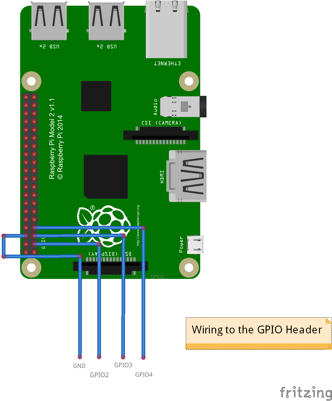
4x GPIO wires (female to male) connected at:
-
GPIO2
-
GPIO3
-
GPIO4
-
GND (ground)
-
-
See, for example, this image of the Raspberry Pi GPIO connector for location information.
-
Connected:
-
Keyboard, mouse and monitor or
-
VNCServer session from PC on the same network as the Pipsta's Raspberry Pi
-
-
Linerless label roll
-
Scissors
-
WiringPi and WiringPi2 installed on the Pipsta/Raspberry Pi. See the readme.md at the bottom of this webpage for instructions. This will be used in the second part of the workshop.
For each student in the workshop, you will need:
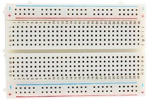
- 1x or 2x 400 point breadboard(s) (also known as a "half+ breadboard"). The quantity depends on the tutor's decision as to whether the both circuit are to be retained intact, or --for reasons of economy-- the first circuit is to be ripped-up prior to assembly of the second.
-
A Pipsta label printed by running the script print_materials.py (it is recommended that this is printed and fitted to the breadboard before the commencement of the workshop)
-
2x Link wires (male to male) example
-
3x 1k ohm resistors
-
1x 330 ohm resistor
-
1x or 2x 5mm red LEDs
Step-by-Step Guide
1) If you haven't done so already, create a new directory under '/home/pi/pipsta/Examples' called 'christmas',
2) Download the file '7_Rudolph.zip' from here to the 'christmas' directory,
3) Right-click the file and select 'Extract Here'
4) You should now see:
• File: print_materials.py - the script that generates the print materials for each student
• File: nose1.py - the script used to operate the first circuit
• File: nose_cct1.png - the image used for the first circuit
• File: nose2.py - the script used to operate the second circuit
• File: nose_cct2.png - the image used for the second circuit
• File: reindeer.png - the presentational layer for BOTH first and second circuits. This fantastic artwork is produced by Felikss Veilands
• Directory: image_print - the image_print module used in previous tutorials, but tweaked to allow the calling script to print the image file rotated (second argument is "1") or unrotated (second argument is "0")
Preparation
1) Print off sufficient labels for each workshop student by navigating to the directory:
/home/pi/pipsta/Examples/14_Christmas/7_Rudolph
...and pressing [F4] to bring up the terminal before entering:
#!python

python print_materials.py
2) Where directed by scissor icon: Cut precisely along the dashed line of the label
3) Fit the Rudolph Nose Circuit 1 label to the breadboard, ensuring it is square by checking the alignment with the last column of holes
4) If they are not already in position from yesterday's tutorial, fit the GPIO wires to the Pipsta/Raspberry Pi. If you are using the Pipsta:
-
Lift the printer out of the top plastics and lay it to one side. You do not need to disconnect the wires
-
Taking heed of the orientation of the GPIO connector, fit the GPIO wires to the Raspberry Pi's pin header:
-
Bring the wires out through the front aperture of the Pipsta housing
-
You may wish to make a note of the colour sequence of the wires or label the unconnected ends
-
Replace the printer in the top plastics.
First Half of Workshop
Kitting
Circuit 1
-
3x 1K resistors
-
2x Link wires
-
1x 5mm LED
Assembly
1) The students are introduced to resistors (blue or beige, two legs), LEDs (red, round, two legs) and link wires. Each component's target location is pointed out (resistors are loosely rectangular, LEDs are loosely circular) in sequence during the assembly .
2) Preparatory advice is given on assembling the circuit, namely:
-
Double-check the flat sides are the right way around
-
Make sure the legs are not bent
-
Push the legs straight down into the breadboard
-
Make sure the legs are pushed all the way down
-
Make sure not to knock any legs out when you put more in
-
Don't worry about the things marked GND, GPIO2, GPIO3, GPIO4 for now
3) The students are asked to assemble the circuit. Allow a maximum of 10 minutes.
4) The tutor should now inspect the circuits. Look for:
-
Completion of circuit
-
Errors in component location
-
Components not pressed all the way home
-
Shorted components (though this is intentionally minimised by the layout)
-
LED orientation
5) Resolve any evident faults
Testing
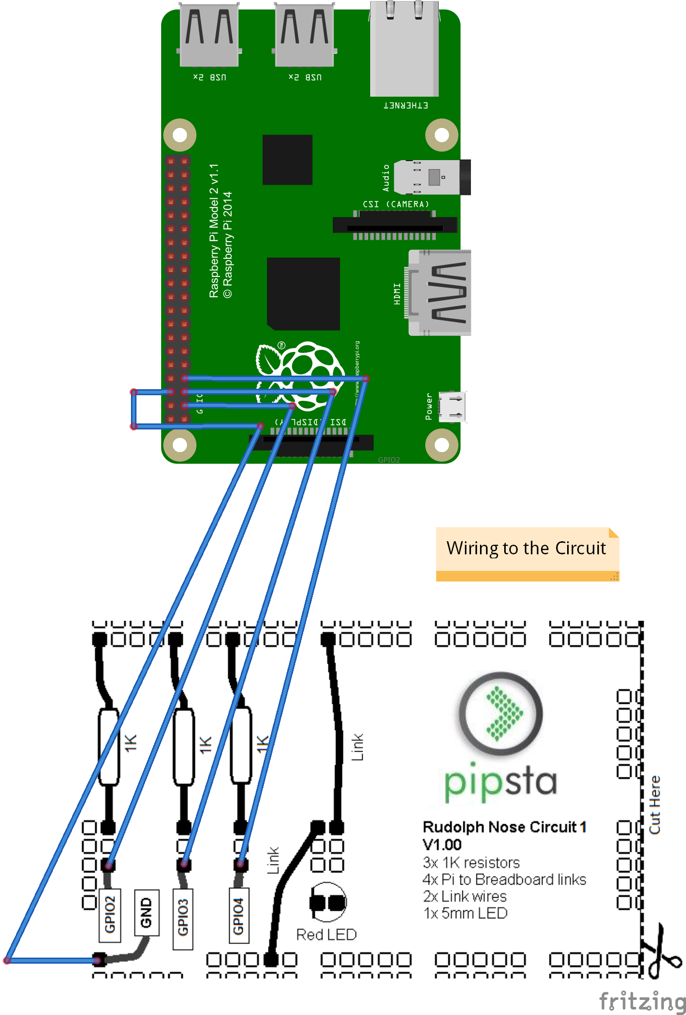
1) After any remedial aspects have been addressed, the tutor should connect each breadboard in turn to the Pipsta/Raspberry Pi:
2) The tutor should now run the script nose1.py. Note that this should be run with Super User privilege to allow access to the GPIO port:
#!python

sudo python nose1.py
3) The LED should light up at increasing and decreasing illumination levels. You may want to slow the time.sleep() period down in the script nose1.py to better illustrate what is going on.
4) If the LED illuminates at 3 different illumination levels, the circuit has been assembled correctly.
Second Half of Workshop
Kitting
Circuit 2
-
1x 330 ohm resistor
-
1x 5mm LED
Repeat all the assembly and testing steps as above, but this time using:
-
The Rudolph Nose Circuit 2 label
-
nose2.py

- Add on the presentational layer to one or both circuits, as required.
How It Works
First Half of Workshop
Last time, we looked at supplying a fixed current to light an LED and discussed the effect of varying the resistance has on the current and illumination level of the LED.
In this project, we have three resistors all connected to a single LED:
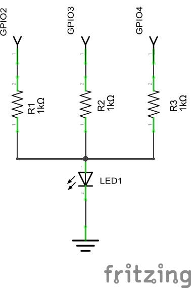
Note that 1K ohm (1000 ohms) is a much higher resistance than the figures we were considering using in the Holly Berries tutorial. You will recall that higher resistance means lower current, so --if one of the GPIO lines was turned on, there would be:
current = Voltage ÷ resistance = 1.6 ÷ 1000 = 1.6milliamps
...flowing into the LED. So the LED will be poorly illuminated with just one of the GPIO lines enabled.
However, we have 3 'branches' available to turn on. Each of these will contribute 1.6milliamps (milliamps is abbreviated to 'mA') for a total of 4.8mA if all lines are enabled, 3.2mA if just two are enabled.
There is a problem with just setting the three GPIO lines high or low, and this is a problem we did not face with the Holly Berry circuit. If some of the GPIO lines are set high and others are set low, the current has an 'easy' path back to ground (the level the low pins will be at), which will mean the LED has its current stolen!
With many design problems like this, there are both software and electronic solutions to this problem.
We talked in the last tutorial about diodes allowing current to flow only in one direction. So we could use diodes to prevent current from returning into the GPIO pins like so:
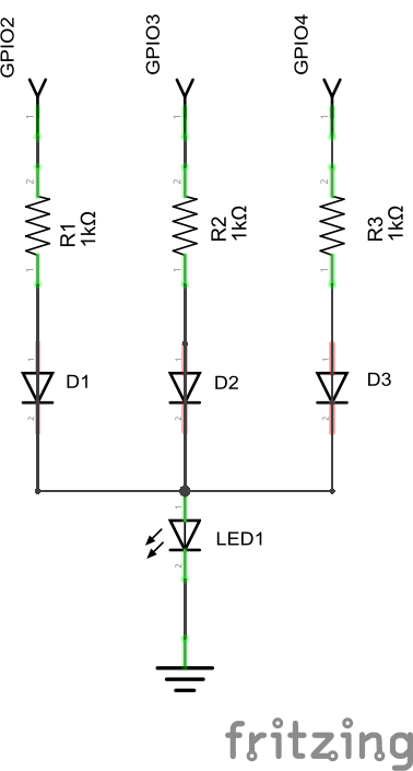
So, if GPIO2 is high and GPIO3 and GPIO4 are low, current will flow from GPIO2, through the resistor, R1, through the diode, D1, to the LED. Even though GPIO3 and GPIO4 are low, current cannot flow to them as D2 and D3 are blocking the flow of current. A such, the LED does not have its current stolen.
Whilst this approach would work, we actually have a 'software' way of making the GPIO pins prevent current flowing back into them-- and one that does not cost us the price of three diodes!
GPIO pins are General Purpose Input and Output pins. When we set them to be input pins, they do not look like high or low signals. They look like very, very high resistances, and we know that very, very high resistances conduct virtually no current. Setting these GPIO pins to be inputs effectively gives us the diode-like blocking we need to ensure all the current goes to the LED's illumination.
In the script nose1.py, you will note a sequence in which not only the levels change between high and low, but the input/output states also change to give the desired effect.
Therefore, the current that the LED sees is either 1.6mA, 3.2mA or 4.8mA, depending on how many lines are high, and outputs. By making the number of enabled GPIO lines increase and then decrease, we get 3 levels of illumination, giving Rudolph's nose its characteristic glow.
There is an optimisation to the circuit and script that would provide seven levels of illumination:
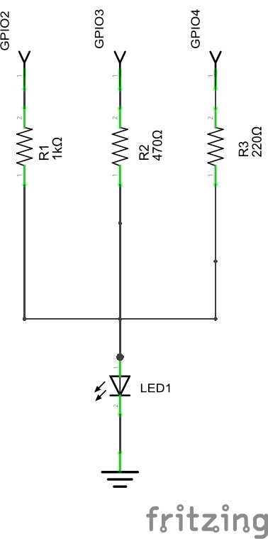
Note that the values of R2 and R3 have changed (these are E12 resistors)
Now, if the script was also to change to enable GPIO lines in a binary counting sequence:
000 001 010 011 100 101 110 111
...the number of levels of illumination would increase in relation to the resistance.
Try modifying the resistances and the script to see the effect of this.
Second Half of Workshop
In this part of the tutorial, the desired increase and decrease in illumination is provided by a single GPIO pin and resistor. Note that the resistor is now once again much lower than the 1K ohm used in the last half of the workshop.
nose2.py basically reduces the illumination by varying the amount of time that the GPIO line is high. This is done at a very high frequency so the eye perceives no flicker.
We actually have very fine (software) control over this effective percentage illumination, and can vary it to a much higher 'resolution' than the electronic solution presented in the first half of the workshop. It is easy, for example, to allow this to vary in increments of 1%, giving a much smoother glow than the electronic solution.
To do this, we use a library function that gives us Pulse Width Modulation (PWM). This effectively means that the width of the high time (with respect to the low time) can be varied over a fixed period. This link shows the concept very well, albeit related to motors.
It can be seen that the electronic component count is much smaller; there are fewer resistors and fewer GPIO lines. It could be concluded that this is therefore a superior design, but the following aspects need to be heeded:
-
The continuing requirement to change from a high to low state can make the microprocessor busier
-
Switching a component that draws appreciable current at very high frequencies can cause interference with other, nearby electronic equipment Electronic products are tested to make sure this interference is limited.
Feedback
We would love to hear back from you about this and any other Pipsta projects. Please drop us a line at support@pipsta.co.uk
[END]
Updated