Wiki
Clone wikiariac / 2017 / frame_specifications
Details of Parts specified in Orders
This page outlines the specifications of the pose requirements specified in each Order.
As outlined in the competition specifications, an Order specifies the list of parts to be put in a kit. Each specified part has the following structure:
- The type of part.
- The position and orientation of the part on the tray.
As specified on the competition interface page, Orders are communicated to teams with the osrf_gear/Order ROS message.
Type of the part
The type of the part is specified as its part name, such as gear_part or piston_rod_part.
The availability of these parts in the workcell may be determined by querying the material_locations ROS service as specified in this tutorial.
Pose of the part on the tray
The pose of the part is composed of the position and the orientation of the part specified in the reference frame of the kit tray. It is communicated in a geometry_msgs/Pose message. The pose of the kit tray frame will vary depending on the kit tray that is used any may vary over time. For example, the pose of the kit trays that are mounted on AGVs will depend on the pose of the AGV itself.
Frame of the tray
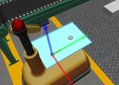
The following image depicts the frame of the kit tray on AGV1.
The x, y, and z axes are represented by red, green and blue markers, respectively.
It has a gear_part with its origin at (x, y, z) = (0, 0.15, 0) (units in meters) and a piston_rod_part at (0.1, -0.2, 0).
Both parts have an orientation of (roll, pitch, yaw) = (0, 0, 0) (units in radians) with respect to the frame of the tray.
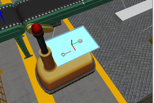
The following image shows the kit tray on AGV1 with two parts on it. In this case,gear_part has a position (x, y, z) = (0, 0.15, 0) (units in meters) and an orientation (roll, pitch, yaw) = (0, 0, 1.57) (units in radians). Piston_rod_part has a position (x, y, z) = (0.1, -0.2, 0) and an orientation (roll, pitch, yaw) = (0, 0, 1.57).
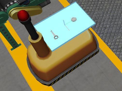
The following image shows the same as above but for AGV2.
Note that the parts still have an orientation of (0, 0, 0) with respect to the frame of the tray, but since the frame itself has a different orientation compared to AGV1, the parts are rotated.
Frame of the part
The pose of the part in the workcell environment will vary over time as the part is moved.
The frame of each part is typically at the center of the part: it can be visualized by clicking on the part in the simulated workcell environment and pressing t: this will display the axes of the frame of the part.
The following figure shows the frame of the gear_part, with the x, y and z axes represented by red, green and blue markers, respectively.
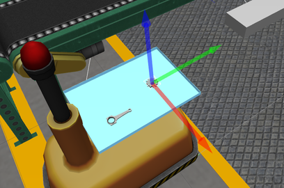
Not all parts have the frame origin at their center: the piston_rod_part, for example, has the origin of its frame off-center, as shown in the following figure.
Flipped parts
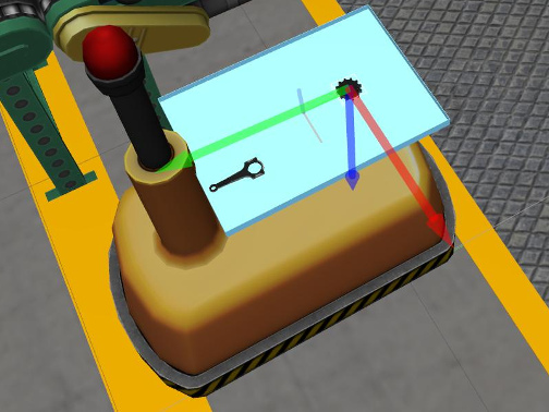
Starting on qualification 3, an order could contain a part that requires to be flipped. More specifically, a part needs to be flipped if there's a substantial difference in roll or pitch between the target orientation and the current orientation of the part. This difference is typically 180 degrees when the part stays on a flat surface leveled with the ground.
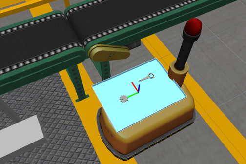
The next image shows the kit tray on AGV1 with two parts that have been flipped from its initial orientation. Gear_part has a position (x, y, z) = (0, 0.15, 0) (units in meters) and an orientation (roll, pitch, yaw) = (3.14159, 0, 0) (units in radians). Piston_rod_part has a position (x, y, z) = (0.1, -0.2, 0) and an orientation (roll, pitch, yaw) = (3.14159, 0, 0).
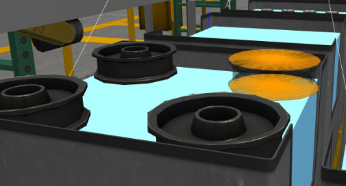
The pulley_part is the only part in the environment designed to be flippable. It has a flat collision surface on its top and bottom ends making it ideal for grasping it with a vacuum gripper. However, the side of the part is hollow, creating a more difficult grasp because of the small contact patch that the edges provide. Teams are not permitted to directly grasp this part from the side when a part flip is required.
Determining the part pose on the tray programmatically
The logical camera reports the pose of parts and trays with respect to the pose of the camera. See the sensor interface tutorial for details of how to use this sensor to programmatically determine the pose of parts on the trays.
Updated